

If you work with lithium polymer (LiPo) batteries—whether you’re designing hardware, building drones or robots, or qualifying suppliers—voltage is the throughline that determines performance, safety, and lifespan. In practice, “What voltage is safe?” or “Why does my pack sag and trigger early cutoff?” are the questions that decide whether a project ships or a weekend build flies.
This guide is the one-stop reference: you’ll learn the fundamentals (nominal vs full vs storage voltage), how to measure correctly (resting vs under load), how to charge with CC–CV, when and how to balance, what cutoffs to use, how temperature changes everything, and how to navigate compliance and transport basics. Where specific numbers matter, we cite authoritative sources so you can configure confidently.
A quick safety note: Li-ion chemistry packs high energy density. Misuse can lead to fire or injury. Always follow charger instructions, never defeat protection circuits, and retire damaged or swollen packs promptly.
1) LiPo voltage fundamentals (what the numbers mean)
When people say a LiPo is “3.7 V,” they’re referring to its nominal voltage—an approximate mid-point of the discharge curve. The usable window is wider and depends on state of charge (SoC), load, and temperature.
- Nominal voltage per cell (OCV near ~50% SoC): about 3.6–3.7 V, per the industry overview in Battery University’s BU-303 (2021).
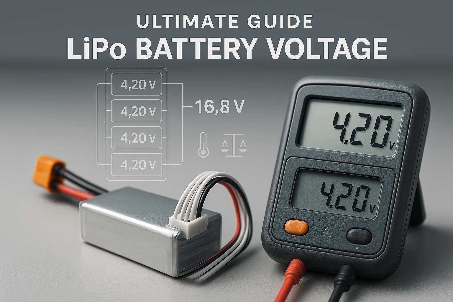
- Fully charged voltage (standard LiPo): 4.20 V per cell, with a common tolerance around ±50 mV, according to Battery University’s BU-409 on charging lithium-ion (2021).
- Storage voltage: roughly 3.7–3.85 V per cell (≈40–60% SoC). Storing around 40–50% SoC is repeatedly recommended in Battery University’s BU-702 (2021).
- Minimum recommended at rest: about 3.0 V per cell; going much below risks copper dissolution and internal shorts, per Battery University’s BU-501 (2021).
A good mental model is to separate open-circuit (resting) voltage from under-load voltage. Under load, the measured voltage dips due to internal resistance and wiring losses and then rebounds as the pack rests—so the same pack can look “empty” under heavy load but read much higher after a minute of rest.
Standard LiPo vs LiHV (4.20 V vs 4.35 V)
There’s a related chemistry variant often sold as LiHV (“high voltage LiPo”) that charges to 4.35 V per cell and lists a higher nominal 3.8 V. This provides more energy per cycle but tends to reduce cycle life compared with standard 4.2 V LiPo; you must also use a charger that supports 4.35 V mode. Manufacturer-facing summaries are available from Grepow’s LiHV pages, which document 3.8 V nominal and 4.35 V max along with representative cycle-life ranges (conditions vary) in their technical briefs: see Grepow 3.8 V/4.35 V LiHV overview (2024) 和 Grepow 3.8 V HV 8C cells page (2025).
Approximate SoC vs resting voltage (25°C)
These are ballpark values at room temperature for a standard LiPo at rest; different cells and loads will shift the curve slightly. Battery University emphasizes that SoC estimation from OCV requires a rest period for accuracy (up to ~90 minutes) in BU-702 (2021).
| SoC (approx.) | OCV per cell (V) |
|---|---|
| 100% | 4.20 |
| 90% | 4.10 |
| 80% | 4.00 |
| 70% | 3.92 |
| 60% | 3.85 |
| 50% | 3.78–3.80 |
| 40% | 3.75 |
| 30% | 3.70–3.72 |
| 20% | 3.62–3.65 |
| 10% | 3.50–3.55 |
| Near empty | ≈3.0–3.3 (avoid deep discharge) |
Note: Treat the lower end conservatively. Prolonged deep discharge below ~3.0 V/cell can cause irreversible damage, as highlighted in BU-501 (2021).
2) Safe limits and protections (how low is too low?)
- Under-load cutoff: For performance and longevity, set your device or BMS cutoff near 3.2–3.3 V per cell under load. This avoids excessive stress from voltage sag and keeps resting voltage above damaging levels. Battery University’s discharge guidance in BU-501 (2021) underpins the conservative approach.
- Absolute minimum at rest: Treat ~3.0 V/cell as a practical floor; repeated deep discharge or leaving a pack empty accelerates degradation and risk, per BU-501 (2021).
- Over-voltage risk: Charging above 4.30 V/cell can trigger plating and gas generation; keep CV set at 4.20 V ±50 mV for standard LiPo, per BU-409 (2021).
If you design with a BMS or protection IC, you’ll see similar thresholds. For example, TI’s BQ2970 protection front-end specifies UV/OV ranges suitable for single-cell Li-ion/polymer; designers typically choose UV around 2.7–3.0 V and OV around 4.2–4.25 V with hysteresis for stability. See the ranges on the Texas Instruments BQ2970 product page.
3) Measuring LiPo voltage correctly (resting vs under-load, sag, and IR)
You might see a pack read 3.6 V/cell under a punchy climb, then “magically” rebound to 3.8 V after landing. That’s voltage sag—current multiplied by internal resistance (and wiring losses). Measuring both at rest and under load gives you the real picture.
- Resting (OCV) measurement: Let the pack rest to relax polarization; Battery University’s BU-702 (2021) recommends allowing up to ~90 minutes for accurate OCV-based SoC. Use a calibrated DMM (±0.5% or better). For multi-cell packs, measure per-cell via the balance connector or via BMS telemetry.
- Under-load measurement: Observe the voltage at a known current. The sag gives a quick estimate of internal resistance: Rinternal ≈ (Vrest − Vload) / I. For accuracy at milliohm levels, use a four-wire (Kelvin) setup or a charger/analyzer that measures IR.
- Why sag matters: Excessive sag triggers early cutoff under load even when resting voltage seems fine—common with aged cells or cold temperatures. Drone and robotics guidance often frames practical limits around these dynamics (see the drone-focused overview in Tyto Robotics, 2023).
Pack math: 1S–6S examples
Multiply per-cell voltage by the number of series cells (S) for a quick pack-level conversion. Below are standard LiPo (4.20 V max) examples:
| Pack | Cells | Full (V) | Nominal (V) | Storage (V) | Conservative under-load cutoff (V) |
|---|---|---|---|---|---|
| 1S | 1 | 4.20 | 3.7 | ~3.8 | ~3.2–3.3 |
| 2S | 2 | 8.40 | 7.4 | ~7.6 | ~6.4–6.6 |
| 3S | 3 | 12.60 | 11.1 | ~11.4 | ~9.6–9.9 |
| 4S | 4 | 16.80 | 14.8 | ~15.2 | ~12.8–13.2 |
| 5S | 5 | 21.00 | 18.5 | ~19.0 | ~16.0–16.5 |
| 6S | 6 | 25.20 | 22.2 | ~22.8 | ~19.2–19.8 |
These are guides, not absolute laws—temperature, C-rate, and chemistry variants shift the working points.
Tools and stack (parity-based, optional)
Disclosure: Yungbang Power is our product.
- 永邦电力 — Custom Li-ion/LiPo packs and BMS design/manufacturing for consumer, industrial, and smart devices; supports certification workflows (e.g., IEC/UL, UN38.3) and OEM integration.
- Measurement: Fluke 87V or comparable DMM (±0.05% DCV class) for accurate per-cell/pack checks; bench scopes/DMMs from Siglent or Keysight also fit.
- RC chargers/analyzers: ISDT and iCharger models with balance charging and IR readout; ensure LiPo vs LiHV mode as applicable.
- Charger ICs/BMS silicon: Texas Instruments BQ-series (e.g., BQ24074 for single-cell charging, BQ76942/52 for multi-cell monitoring and passive balancing—confirm datasheet features for your voltage and cell count).
Language in this toolbox is neutral and role-based; use what fits your build and compliance plan.
4) Charging the right way: CC–CV, current, and termination
Standard LiPo uses a two-stage CC–CV profile: charge at a constant current until the cell reaches 4.20 V, then hold 4.20 V and allow current to taper to a termination threshold. This is the baseline across reputable sources, including Battery University’s BU-409 (2021).
- Charge current (C-rate): 0.5C–1C is common; 0.5C is gentler and sufficient for most use cases. See fundamentals and examples spanning BU-409 and charger IC datasheets such as the Texas Instruments BQ24074 (Rev N, 2021).
- Termination current: Many systems stop near 0.05C–0.1C; lower termination improves longevity at the expense of charge time, a trade-off discussed in BU-409 (2021).
- Temperature windows: Charging is best around 10–30°C for longevity; acceptable in many specs from 0–45°C, with reduced current near the limits. See Battery University BU-410 (2022) and manufacturer application notes such as Renata’s LiPo guidelines (2023).
- No trickle/float at high voltage: Avoid keeping cells at 4.20 V/cell indefinitely. Elevated voltage combined with time and temperature accelerates aging. Battery University BU-808b (2021) aggregates experimental evidence on voltage stress.
LiHV note: Only charge to 4.35 V if your cell is specified for it and your charger explicitly supports LiHV mode. Some chargers offer adjustable CV setpoints; verify against the datasheet and do a test qualification.
Checklist (charging setup):
- Confirm chemistry/mode (LiPo 4.20 V vs LiHV 4.35 V)
- Set series count (S) correctly and connect balance leads
- Choose current (start with 0.5C; reduce in cold weather)
- Verify temperature in range before charging; warm or cool the pack if needed
- Use termination around 0.05C–0.1C; disconnect after charge (no prolonged float)
5) Balancing cells and BMS thresholds
Multi-cell packs drift over time; a weak cell empties first and hits protection limits early. Balancing realigns per-cell charge so the pack as a system behaves predictably.
- Why balance: It prevents a single cell from overcharging or over-discharging relative to its neighbors, avoids capacity loss from early limits, and preserves safety margins.
- When to balance: Most hobby chargers perform top-of-charge balancing; some systems can also balance during CV or even at rest. Passive balancing bleeds small current from higher-voltage cells; active balancing (more complex) shuttles charge between cells.
- BMS thresholds: Practical ranges for UV around 2.7–3.0 V and OV around 4.2–4.25 V per cell, with hysteresis, are common in LiPo designs; see ranges exemplified by the TI BQ2970 protection IC. For multi-cell monitors with balancing, Texas Instruments’ BQ76952 datasheet (2021) 和 BQ76942 datasheet (2021) detail configurable balancing and protections, and their app note SLUAA81A (2022) explores balancing methods and design considerations.
In practice, set thresholds based on your load profile, cable/connector drops, and cell behavior across temperature—then validate with worst-case tests.
6) Storage and longevity (why 3.8 V matters)
Storing LiPo at full charge in a warm garage is a recipe for rapid aging. Two levers dominate: average state of charge and temperature.
- Storage voltage: Target ~3.7–3.85 V/cell (≈40–60% SoC). This is a widely recommended range for minimizing chemical stress during dormancy; see Battery University BU-702 (2021).
- Temperature: Store cool and dry—room temperature or lower. Elevated temperature accelerates side reactions exponentially (Arrhenius). Reviews of degradation mechanisms confirm high SOC + high temperature is especially harmful; for an accessible synthesis, see Shi et al. review (2025) 和 Shen et al., ACS Omega (2022).
- Reduced charge voltage extends cycle life: Limiting the maximum charge to 4.10 V/cell can markedly improve longevity, especially at higher temperatures, as summarized in Battery University BU-808b (2021) and discussed in BU-409 (2021).
Storage checklist:
- Use charger’s storage mode to reach ~3.8 V/cell
- Label packs with date and last state (e.g., “Apr: 3.82 V/cell”)
- Store in a fire-resistant container, away from heat sources
- Every 2–3 months, verify voltage; top up to storage level if needed
7) Temperature, performance, and aging (operating windows)
Temperature reshapes performance in predictable ways:
- Charging window: Best around 10–30°C; many cells allow 0–45°C charging with reduced current near the edges. Low-temperature charging risks lithium plating—avoid below ~0–5°C unless your system explicitly supports it. See Battery University BU-410 (2022) 和 Renata guidelines (2023).
- Discharge window: Commonly -20 to 60°C. Expect less power at low temperatures and faster aging at high temperatures; see BU-410 (2022).
- High SOC + heat = fastest aging: Parking at full voltage in a hot car accelerates capacity loss and raises risk; reviews collate acceleration factors under various stressors, e.g., Shi et al., 2025.
Practical tip: If your application regularly runs hot, consider limiting charge to 4.10–4.15 V/cell and validating that the reduced runtime still meets requirements—often the trade yields a net lifecycle gain.
8) Troubleshooting: swelling, imbalance, early cutoff, high IR
You might encounter one or more of these failure modes as packs age or if they’re misused. Here’s how to recognize and respond.
Swelling (gas generation)
- What you’ll see: Soft or hard swelling of pouches, warm packs, chemical smell.
- Causes: Overcharge, over-discharge, overheating, internal short, physical damage, or manufacturing defects.
- What to do: Do not charge or compress. Isolate the pack, avoid puncture, and arrange proper recycling/disposal. University EHS programs explain safe handling steps, e.g., University of Reading EHS guidance (2023) 和 Princeton EHS overview (2024).
Chronic imbalance
- Symptom: One cell consistently reads higher/lower after charge/discharge.
- Root causes: Unequal cell aging/capacity, lack of balancing, or BMS issues.
- Actions: Perform a full balance charge; inspect wiring/connectors; check BMS configuration; retire the pack if imbalance worsens despite balancing.
Early cutoff under load (but OK at rest)
- Symptom: System shuts down during bursts, yet resting voltage looks healthy.
- Root causes: High internal resistance in one or more cells, cold temperatures, or undersized wiring/connectors.
- Actions: Measure under-load voltage; estimate IR via R ≈ (Vrest − Vload)/I; compare across cells (via balance tap) to find the weak link. Consider replacing the pack or re-terminating high-resistance connectors.
When to retire a pack
- Visible swelling, persistent imbalance (>50–80 mV at rest after balancing), or significantly elevated IR compared with new baseline are retirement cues. Follow local rules for recycling; skip outdated “saltwater discharge” advice. US guidance treats spent Li-ion as hazardous or universal waste; see EPA-related summaries (2023–2025), e.g., AFSlaw overview of EPA guidance (2023) and updates on universal-waste considerations in Nixon Peabody (2025). For consumer drop-off, programs like Call2Recycle’s locator and retail partners such as Home Depot x Call2Recycle (2021) can help.
9) Compliance and transport at a glance
If you build or ship products with LiPo packs, voltage and SoC are only one part of a compliance story that includes testing, packaging, and documentation.
- UN38.3 testing: All lithium cells and batteries must meet UN Manual of Tests and Criteria Section 38.3 (T.1–T.8: altitude, thermal, vibration, shock, external short, impact/crush, overcharge, forced discharge). PHMSA’s resources and the UN test summary requirement outline manufacturer obligations for products made after Jan 1, 2008; see the PHMSA Lithium Battery Guide for Shippers (2023) 和 Test Summary brochure (2022). For an engineering overview of the test sequence and purposes, see SwRI UN38.3 summary (2022).
- IATA/ICAO air transport (2025): Lithium-ion cells/batteries shipped by air must follow IATA DGR packing instructions. UN3480 (batteries alone) are restricted to SoC ≤30% under PI 965; equipment-related shipments use PI 966/967. Consult the current IATA Lithium Battery Guidance Document (2025) and DGR updates in IATA’s knowledge hub (2025). Passenger carriage limits are summarized in IATA passengers with lithium batteries (2025).
- Standards landscape: Many markets expect IEC 62133-2 for portable secondary lithium batteries; UL 1642 (cells) and UL 2054 (packs) are common in North America. For high-level scope and differences, see accessible overviews such as Labtest/UL Solutions battery standards explainer and targeted articles like ComplianceGate’s UL 1642 overview (2022). Some industry explainers also contrast IEC 62133 vs UL 2054 (2025); always verify against the latest official standard text.
Documentation tip: Retain UN38.3 test summaries from your supplier, declare watt-hours (Wh) accurately, and align pack labeling with DGR/ADR/IMDG specifics for your routes.
10) Putting it all together: practical workflows
Below are short, field-tested workflows you can adapt.
Charging workflow (standard LiPo):
- Verify pack health (no swelling/damage; cells within ~20–30 mV of each other at rest)
- Select LiPo 4.20 V mode; set S-count; connect balance lead
- Start at 0.5C (reduce for cold packs); set termination around 0.05C–0.1C
- Monitor pack temperature; stop if any cell exceeds safe limits
- Disconnect after reaching full; avoid sitting at full charge for hours
Storage workflow:
- Run charger’s storage program to ~3.8 V/cell
- Label and date; store cool in a fire-resistant container
- Recheck every 2–3 months; adjust back to storage level if drifted
Cutoff calibration (device/BMS):
- With a known load, log per-cell under-load voltage and current
- Estimate IR for each cell: (Vrest − Vload)/I; identify weak cells
- Set LVC around 3.2–3.3 V/cell under your peak load; validate at low temperature
- Add hysteresis/time filters to avoid nuisance trips on short spikes
Troubleshooting quick checks:
- Early cutoff? Compare under-load vs rest; check connectors; measure cell IR
- Imbalance? Perform a full balance charge; recheck after a rest period
- Swelling? Stop use immediately; arrange proper recycling
11) Frequently asked questions
- Is 3.7 V “half full”? Roughly yes at room temperature, but OCV-to-SoC mapping varies by cell and requires rest for accuracy. See Battery University BU-702 (2021).
- Can I discharge below 3.0 V/cell? It’s strongly discouraged; BU-501 (2021) explains the damage mechanisms at very low voltages.
- Should I always balance? For multi-cell packs, yes—regular balance charging helps keep cells aligned and protects against uneven aging. TI’s BQ769x2 app note (2022) covers balancing strategies.
- Is LiHV worth it? If you need a bit more energy and accept potential cycle-life trade-offs, maybe. Use a 4.35 V-capable charger and validate endurance with your duty cycle. See vendor tech briefs like Grepow LiHV overview (2024).
12) Sources and further reading
- Core voltage, charging, storage, and temperature behavior: Battery University BU-303, BU-409, BU-410, BU-501, BU-702, BU-808b
- Charger IC example: Texas Instruments BQ24074 datasheet (2021)
- BMS/monitoring and balancing: TI BQ2970, TI BQ76952, TI BQ76942, TI balancing app note SLUAA81A
- LiHV orientation: Grepow LiHV 3.8 V overview, Grepow HV 8C page
- Compliance/transport: PHMSA Lithium Battery Guide (2023), PHMSA Test Summary brochure (2022), IATA Lithium Battery Guidance 2025, IATA DGR updates 2025, IATA passengers with lithium batteries (2025)
- Safety/EOL handling: University of Reading EHS swollen battery guidance (2023), Princeton EHS lithium battery safety (2024), AFSlaw summary of EPA guidance (2023), Nixon Peabody update (2025), Call2Recycle locator
By separating resting vs under-load voltages, setting conservative cutoffs, charging with CC–CV in the right temperature windows, balancing regularly, and storing near 3.8 V/cell, you can dramatically reduce surprises and extend pack life. Validate with your exact loads and environment—and keep safety and compliance in the loop from day one.