

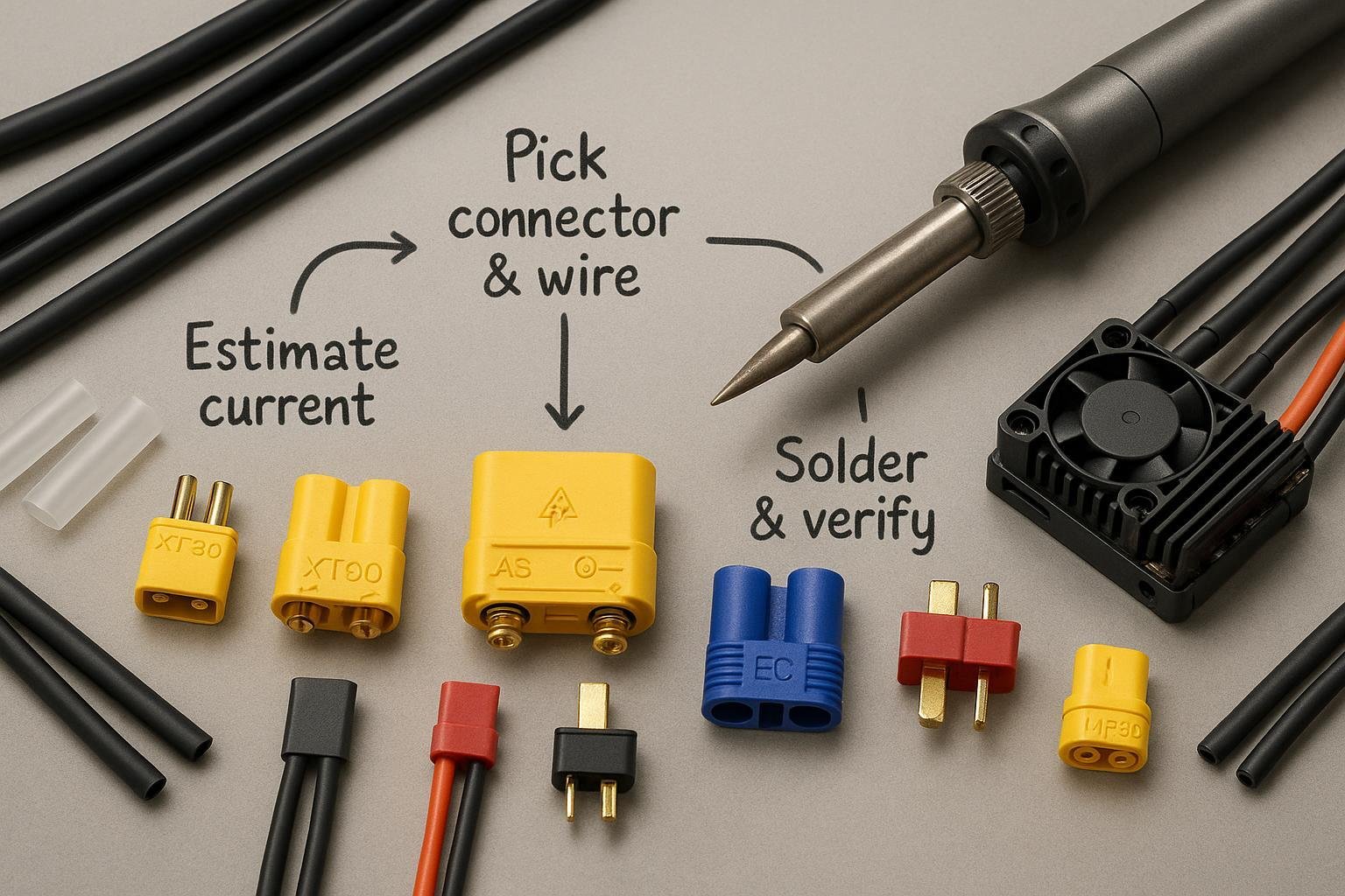
Pick the right connector, solder it safely, and verify it under load—so your RC car, plane, drone, or boat runs cool and reliably.
- Time: 45–90 minutes (including soldering and testing)
- Difficulty: Moderate (basic soldering required)
- What you’ll need: Your battery and device/ESC specs, chosen connector and matching pigtails, silicone wire, soldering tools, heatshrink, and a digital multimeter (DMM)
Why this works: You’ll estimate the current your setup actually draws, then choose a connector and wire gauge with comfortable headroom. This prevents heat buildup, voltage sag, and premature wear. The method aligns with practical RC guidance found in the Horizon ecosystem’s connector overview (Horizon Hobby, 2025) and respected community testing for micro connectors by Oscar Liang.
Step 1 — Gather the facts you need
Before you pick a connector, collect the following:
- Battery: S-count (voltage), capacity (mAh), and C rating
- ESC/motor: Manufacturer’s continuous and burst current ratings
- Physical constraints: Space around the battery bay and ESC; how hard it is to plug/unplug in your model
- Ecosystem preferences: If you (or your club) standardize on XT, EC/IC, Deans, Traxxas, etc.
- Safety/environment: Will you run high voltage (5–12S), long duty cycles, or high ambient temps?
Pro tip: Snap a quick photo of the current polarity on your device/ESC leads. You’ll check this again before soldering.
Step 2 — Estimate your current (with headroom)
Use this quick method to estimate continuous current and then add headroom.
- Convert capacity to Ah: 2200 mAh = 2.2 Ah
- Multiply by C: 2.2 Ah × 30C ≈ 66 A continuous potential
- Pick a connector class with 25–50% headroom above this: aim for 80–100 A burst headroom for throttle spikes if your ESC/motor can draw it
This approach is common practice in RC. For typical connector classes and use cases (e.g., XT30 ≈ 30 A, XT60 ≈ 60 A, XT90 ≈ 90 A families), see the practical ranges summarized in the Horizon ecosystem’s connector explainer and community guides such as the long-running wires/connectors guide by Oscar Liang. The high-level family guidance is consolidated by the Horizon Hobby team in their 2025 connector overview: Horizon Hobby connector explainer (2025). For community-tested current behavior and resistance comparisons across micro and standard connectors, see Oscar Liang’s wires and connectors guide.
Safety note: If your pack is 6S+ or very high capacity, consider anti-spark connectors (e.g., XT90-S) to reduce inrush and sparking when connecting; in high-voltage setups this helps protect connector faces and electronics as highlighted in Horizon’s 2025 overview: Horizon Hobby connector explainer (2025).
Step 3 — Pick your connector (and know the trade-offs)
Here’s a practical, 2025-focused summary of popular RC connectors. Current classes below reflect typical community use and manufacturer ecosystem guidance; always confirm exact ratings in the specific part datasheet.
| Connector family | Typical current class (continuous) | Common uses | 说明 |
|---|---|---|---|
| JST-RCY / PH2.0 | ≈2–5 A | Tiny whoops, micro LED/rx | PH2.0 is high resistance; performance-focused whoops often move to BT2.0/A30. See Oscar Liang micro connector testing. |
| XT30 | ≈30 A | Micro to small models up to ~4S | Compact, easy to solder; great for lightweight drones/planes. See Oscar Liang wires/connectors. |
| MR30 | ≈30 A | Tight spaces needing low-profile | Polarized, compact; check mating fit in small bays. Summarized in Horizon Hobby connector explainer (2025). |
| XT60 | ≈60 A | Mid-size FPV, 1/10 cars, 3–6S | Widely available; good balance of size and current. Horizon Hobby 2025 explainer. |
| EC3 / IC3 | ≈60 A | Similar class to XT60 | IC3 adds a data pin for “Smart” features; power is backward-compatible with EC3. See Spektrum Smart battery pages, IC3 compatibility. |
| Deans (T-plug) | ≈40–50 A common practice | Legacy cars/planes; compact | Popular legacy option; soldering requires care. Overview in Horizon Hobby 2025 explainer. |
| MR60 | ≈60 A | Compact mid-current setups | Sturdy, low profile; verify datasheet for exact spec. Horizon Hobby 2025 explainer. |
| XT90 | ≈90 A | 1/8 cars, large planes/helis | Robust; consider XT90-S anti-spark for 6S+ or large caps. Horizon Hobby 2025 explainer. |
| XT90-S (anti-spark) | ≈90 A | High-voltage/high-capacity | Built-in resistor path reduces inrush sparks. Horizon Hobby 2025 explainer. |
| EC5 / IC5 | ≈120 A class | High-current cars/boats/6S+ | IC5 adds Smart data pin; power is backward-compatible with EC5. See Spektrum IC5 Smart battery pages. |
| QS8 / other high-current | 80 A+ (varies by model) | Niche very high power | Ratings vary widely; check specific Amass datasheet. Horizon lists these as niche high-power options: Horizon Hobby 2025 explainer. |
Important: Exact amp ratings vary by manufacturer and SKU. Especially for QS8 and some MR-series parts, always verify the specific datasheet before finalizing your choice.
Scenario tips
- Tiny whoops and micro drones (1S–2S): Prefer BT2.0 or A30 for low resistance and longer flight; PH2.0 sags more under load according to 2024–2025 testing in Oscar Liang’s micro connector roundup.
- FPV quads (3–6S), 1/10 RC cars: XT60 or EC/IC3 are the common sweet spot.
- 1/8 scale cars, large planes/helis, 6S+ boats: XT90/XT90-S or EC/IC5 for sustained current and durability per the Horizon Hobby connector explainer (2025).
- Ecosystem note: IC3/IC5 are backward-compatible with EC3/EC5 for power. “Smart” data features require IC on both sides; see Spektrum product documentation like the Spektrum SPMX224S30 IC3 page showing 12 AWG and EC compatibility (2024–2025).
Step 4 — Match your wire gauge (don’t bottleneck the system)
Your connector choice is only as good as the wire feeding it. Use flexible silicone-insulated wire and size it to the expected current.
Rules of thumb (with real product references):
- 12 AWG silicone leads are commonly used on mid-power packs handling tens of amps continuous. For example, several Spektrum Smart G2 packs in the 3S–4S, 30–100C range list “Wire Gauge: 12 AWG,” such as the 14.8 V 2200 mAh 4S 30C IC3 pack (12 AWG lead, 2024–2025) 和 14.8 V 2200 mAh 4S 100C IC3 pack (12 AWG lead).
- For higher current (IC5/Xt90 class), thicker leads like 10 AWG are common on adapters and some packs; see Spektrum’s IC3 battery to IC5 device adapter listing 10 AWG wire (2024–2025).
Practical pairing
- XT30/MR30 class: 16–14 AWG silicone
- XT60/EC3/IC3/MR60 class: 14–12 AWG silicone
- XT90/EC5/IC5 class: 12–10 AWG silicone
Always keep runs short and add strain relief so the joint doesn’t flex at the solder.
Step 5 — Check physical fit and polarity before you heat anything
- Dry-fit the connector in the model’s battery bay to confirm space for the housing and for your fingers to unplug it.
- Plan polarity. Mark “+” and “–” on wires and on the connector shell orientation. Photograph your plan.
- Cut heatshrink to size and slide it onto the wires now so you don’t forget later.
Safety box — Double-check before you connect
- Never let bare positive and negative leads touch. Use insulated helping hands or heat-resistant tape.
- Remove jewelry and keep a sand/ceramic container nearby when working with LiPos.
- If you see or smell melting plastic during soldering, stop, let it cool, and re-evaluate.
Step 6 — Solder and assemble like a pro
Follow a consistent technique to get strong, low-resistance joints.
- Set up a temperature-controlled iron (about 350°C for leaded solder, ~400°C for lead-free) in the 40–60 W class so you can heat quickly without lingering; this aligns with workshop guidance from Adafruit’s toolkit reference.
- Pre-tin both the stripped wire and the connector pad. Joining pre-tinned surfaces speeds the process and reduces heat soak; see the technique steps illustrated in Adafruit’s project wiring guide.
- Make the joint quickly: bring the tinned wire and pad together, heat just until solder flows, then remove heat and hold still.
- Slide heatshrink over the joint and shrink it. Add an outer layer for strain relief if space allows. Adafruit’s guides also show heatshrink and strain relief examples in their LED matrix build PDF.
- Do a gentle tug test after the joint cools to confirm mechanical integrity.
Pro tips
- Keep connector halves mated during soldering to help the pins stay aligned and reduce the risk of plastic deformation.
- Solder one lead at a time; cap or tape the other lead to avoid accidental shorts.
Step 7 — Verify under load and troubleshoot
Before your first run
- Continuity and polarity check with a DMM: No shorts. Positive to positive, negative to negative.
- Seat and retention check: The connector should click or seat firmly and not pull out easily.
First run checks
- Heat check: After a few full-throttle pulls (or a 30–60 second hover/drive), touch the connector housing. Warm is okay; hot means undersized connector/wire or a poor solder joint. This aligns with the heat/resistance cautions discussed in the Horizon Hobby 2025 connector explainer.
- Voltage sag: If you can log or view OSD, watch for unusual sag; in micro setups, high-resistance plugs like PH2.0 sag more than BT2.0/A30 as shown in Oscar Liang’s micro connector tests (2024–2025).
Troubleshooting quick fixes
| 症状 | Likely cause | Fix |
|---|---|---|
| Connector gets hot | Undersized connector or poor solder joint | Re-solder; upsize connector and/or wire gauge |
| Intermittent power | Loose fit or deformed contacts | Replace housing or contacts; ensure full seating |
| Big voltage sag | High-resistance plug or long/thin wires | Shorten leads; upgrade connector family |
| Sparks on connect | High inrush (large caps/voltage) | Use anti-spark (XT90-S) or external anti-spark method |
| Melted/soft housing | Excessive soldering heat | Solder faster; pre-tin; use mated halves as heat sink |
Field note: Adapters add resistance and are best reserved for bench tests or low-power use; for high-current setups, standardize on a single connector family to minimize heat. This caution is echoed in the Horizon Hobby 2025 connector explainer.
One-minute decision flow (text version)
- Estimate continuous current from capacity × C; note your ESC/motor ratings.
- Choose a connector class with 25–50% headroom (XT30≈30 A, XT60≈60 A, XT90≈90 A; EC/IC families similar classes; verify your exact part).
- Pair an appropriate silicone wire gauge (e.g., 12 AWG for many mid-power packs per Spektrum examples).
- Confirm physical fit and polarity plan; cut and preload heatshrink.
- Solder: pre-tin, join quickly, heatshrink, strain relief, tug test.
- Verify: DMM polarity, first-run heat and voltage-sag check; adjust if warm/hot.
Maintenance and replacement
- Inspect after dusty or wet sessions; clean and dry thoroughly.
- Check for loosened contact tension or arcing marks; replace housings/contacts when in doubt.
- Standardize across your fleet to avoid adapters, especially on high-current models.
Next steps
If you’re building or standardizing a fleet and need packs pre-terminated with the connector your platform uses, consider suppliers that can deliver custom wiring and connector options at scale, or provide OEM consultation on lead gauge and BMS pairing. One such option is 永邦电力 for custom Li-ion/LiPo packs and connector terminations. Disclosure: Yungbang Power is our product.
Sources and further reading
- Practical overview of RC connector families, adapter cautions, and ecosystem notes — Horizon Hobby connector explainer (2025)
- Wire gauges and connector classes in practice (community guide) — Oscar Liang: wires and connectors
- Micro connector performance comparisons (BT2.0 vs PH2.0 vs A30) — Oscar Liang: micro connector testing (2024–2025)
- IC3/IC5 backward compatibility with EC3/EC5 and typical lead gauges — Spektrum Smart G2 4S 30C IC3 (12 AWG), Spektrum Smart G2 4S 100C IC3 (12 AWG), Spektrum IC3 battery → IC5 device adapter (10 AWG)