

Overcharging is one of the most common precursors to lithium-ion battery failures. In practice, it’s rarely one mistake; it’s a chain: an overly permissive charger, drifting voltage sensing, lack of per-cell protection, and absent thermal guardrails. This article distills field-proven methods to break that chain—so engineers, safety managers, and OEM teams can prevent thermal events without derailing product performance or timelines.
What “overcharge” actually does inside the cell
In controlled lab tests and post-incident analyses, the hazards come from a few well-understood mechanisms that accelerate once a cell is pushed past its upper charge limit.
- SEI breakdown and side reactions: The solid electrolyte interphase on the anode decomposes at elevated voltage/temperature, exposing fresh surface and triggering exothermic reactions. A 2021 peer-reviewed study quantified the composition and flammability of gases released during thermal runaway across chemistries, underscoring how overcharge-driven reactions create ignitable mixtures; see the open-access analysis in Li et al. 2021 on eruption gas fire boundaries.
- Lithium plating and dendrites: When charge rate or voltage outpaces intercalation kinetics, metallic lithium can plate on the anode and form dendrites, capable of piercing the separator and shorting the cell.
- Electrolyte oxidation and gas generation: Elevated cathode potential oxidizes solvents/salts, producing CO2 and hydrocarbons that increase internal pressure and cause swelling/venting.
- Cathode decomposition and oxygen release: Layered oxides (e.g., NMC/NCA) can release lattice oxygen at high state of charge and temperature, accelerating self-heating and pushing the cell toward thermal runaway; LFP is more thermally stable but not immune to overcharge damage.
Typical progression observed in abuse testing:
- ~70–90°C: SEI breakdown and side reactions begin
- ~110°C: Organic solvent decomposition and vigorous gas evolution
- ~130–140°C: Separator softening/melting; internal short risk increases
-
200°C: Cathode decomposition and oxygen release; runaway self-heating
The safe upper voltage is chemistry-specific. Representative manufacturer data show:
- NMC/NCA cylindricals (e.g., Panasonic NCR18650 family): 4.20 V per cell max in CC/CV charging per the Panasonic NCR18650B datasheet.
- LFP cells (e.g., A123 ANR26650): 3.60 V per cell typical CCCV limit per the A123 ANR26650M1-A datasheet.
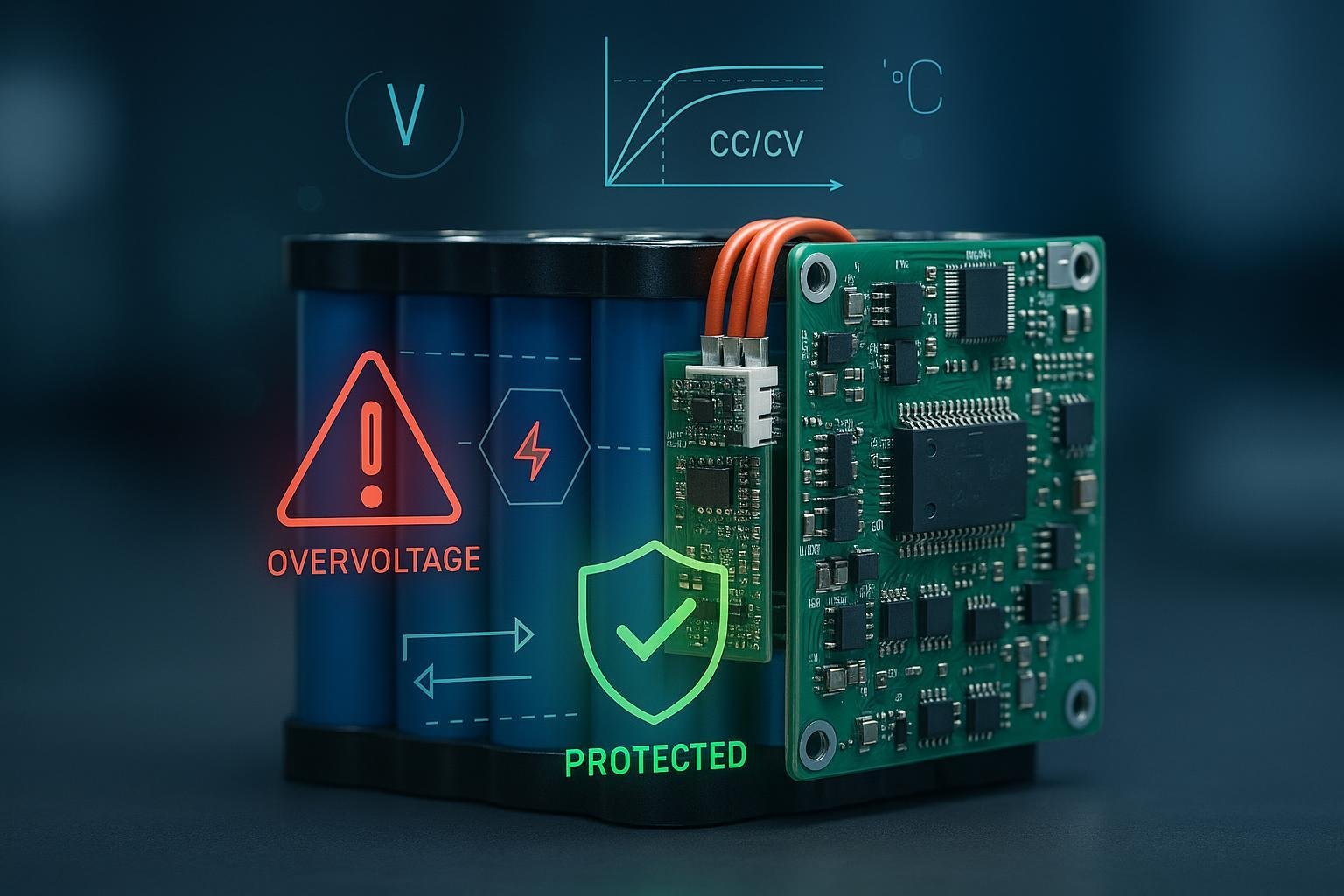
Charging best practice uses CC/CV with tight tolerances (often ±50 mV per cell) and a current taper cutoff near 0.05C at the constant-voltage stage, as summarized in Battery University’s 2025 guidance on charging Li-ion.
2025 incident context: what recent cases reinforce
- According to the Fire Department of New York (FDNY), structural fires linked to lithium-ion batteries increased by 53% year-over-year in early 2025, prompting a renewed push to use listed equipment and avoid unattended charging; see the FDNY 2025 PSA and advisory.
- U.S. Consumer Product Safety Commission actions continue to emphasize inadequate protection and overheating/overcharge hazards. For example, a July 2025 action reports 14 overheating incidents and three fires tied to a micromobility battery, detailed in the CPSC recall notice for VIVI e-bike batteries (2025).
- Large-scale ESS incidents remind us that system integration matters as much as cell chemistry. Following the January–February 2025 fire events at an energy storage site in California, the U.S. EPA coordinated the largest lithium-ion cleanup in the agency’s history; root-cause findings were still pending publicly at the time of writing. Reference the EPA’s Moss Landing response page for official updates.
These public records don’t prove a single universal cause, but they consistently point to gaps in charging control, protection layers, and operational discipline as recurring risk factors.
Engineering best practices to prevent overcharge events
The fastest way to reduce overcharge risk is to combine per-cell electrical protections, robust charger profiles, and thermal guardrails—then verify them through standards-based testing.
- Set chemistry-correct OVP/UVP and charger profiles
- Use the cell datasheet as the source of truth. For many NMC/NCA cells, OVP should clamp near 4.20 V per cell; for LFP, near 3.60–3.65 V. Define CC/CV charge with tight voltage tolerance (e.g., ±50 mV/cell) and a CV-stage termination current around 0.05C. Where energy throughput allows, consider slightly lower charge voltage to reduce stress without unacceptable capacity loss.
- Monitor at the cell level with hardware-backed cutoffs
- Implement per-cell measurement and a primary protection path capable of physically disconnecting charge (e.g., FETs/contactors). Add small hysteresis to OVP thresholds to prevent chatter. A representative AEC-proven monitor/protector is documented in the Texas Instruments BQ79616 datasheet, which combines cell monitoring, balancing, and FET drivers.
- Select capable suppliers and validate protections upfront
- For OEM/ODM builds, confirm that your manufacturing partner can implement and validate cell-level OVP/UVP, proper CC/CV, and thermal interlocks, and can produce conformity evidence for safety standards. See capabilities at Yungbang Power. Disclosure: Yungbang Power is the publisher of this article.
- Balance cells to keep SOC aligned under charge
- Passive balancing (bleed resistors) is sufficient for many small to mid-size packs and is simpler to validate. Active balancing can reduce heat and improve charge efficiency in larger or high-C-rate systems but adds complexity and potential failure modes; reserve it for where ROI is clear and the design team has the experience to validate edge cases.
- Enforce temperature windows and derating
- Charge cells only within the datasheet temperature window (commonly near 0–45°C, but verify for your chemistry). Integrate multiple NTCs/RTDs per module, pause or derate charging when cell or ambient temperature rises, and ensure adequate heat sinking and airflow—especially near end-of-charge when exothermic reactions increase.
- Build in physical safety devices and fusing
- Cell-integrated devices like CIDs and PTCs can interrupt current under internal overpressure or temperature rise, while pack-level fuses and TVS clamps provide last-resort protection. Size fuses relative to maximum fault energy and BMS thresholds; consider pyro-fuses/dual-contactors in high-energy systems for fail-safe isolation.
- Validate against recognized safety standards
- Use accredited labs to run overcharge and single-fault testing aligned to IEC 62133-2 for portable batteries, with ESS-level designs including propagation testing under UL 9540A. For a practical overview of test expectations and setup, see this concise summary of IEC 62133-2 testing. Retain complete reports as part of your compliance file.
- Prove the charger–BMS handshake and failure behavior
- System-test with the actual charger and BMS: induce communication loss, sensor drift, and overvoltage injection to validate each layer’s response. Confirm charger output clamps, BMS cutoff action, and fuse clearing behavior are deterministic and logged.
- Document setpoints, tolerances, and rationale
- Record OVP/UVP values, hysteresis, thermal limits, and timer/logic settings. Document the safety case: why tolerances are set as they are, and how they relate to the datasheet and test evidence. Make these documents part of design reviews and supplier PPAPs.
Charger and power-path controls that actually hold the line
A robust battery design can still be compromised by a charger that ignores or cannot enforce limits. Tie charger selection and validation to safety outcomes.
- Stick to CC/CV chargers that can reliably meet your per-cell limits through pack-level control and BMS communication. The industry-standard profile and tolerances are summarized in Battery University’s 2025 CC/CV explainer.
- Confirm listing/certification appropriate to the application (e.g., UL 1310 Class 2 or UL 62368-1 for ICT/AV power units; IEC 60335-2-29 for household chargers). Require test evidence of overvoltage protection and thermal cutback.
- Validate protection stacking: charger output clamp, BMS FET cutoff, and pack fuse coordination. Intentionally inject faults (e.g., sensor open/short, charger runaway) to observe safe, predictable shutdown and log creation.
- For multi-series packs, ensure per-cell protection logic remains authoritative. A pack-level voltage limit is not a substitute for cell-level OVP.
Operational safety management: policies that prevent surprises
Engineering controls need operating discipline to match. Field rules from safety agencies highlight the simplest ways to cut risk:
- Use listed batteries and the manufacturer-specified charger; avoid unlisted or mismatched power supplies. FDNY’s 2025 messaging underscores this and advises against unattended charging; see the FDNY 2025 PSA.
- Avoid overnight or unattended charging. Charge in a cool, ventilated, non-flammable area, and keep egress paths clear.
- Inspect for damage: stop using any battery that is swollen, hot when idle, has impact damage, or shows corrosion. Quarantine suspect units and recycle through approved channels.
- Store at moderate state of charge (often ~30–50%) and away from heat sources; follow chemistry-specific recommendations.
- Monitor recall notices and vendor advisories. The CPSC’s 2025 recall of VIVI e-bike batteries is a reminder that if protections aren’t sufficient, incidents and product actions follow.
Trade-offs and pitfalls practitioners should anticipate
- Chemistry trade-offs: LFP generally offers higher thermal stability and lower oxygen release under abuse than NMC/NCA. The trade-off is lower volumetric energy density. For constrained enclosures or consumer indoor use, LFP can reduce worst-case severity, but overcharge protections remain mandatory.
- Nuisance trips vs. real safety margins: Aggressive OVP with minimal hysteresis can cause chatter and user complaints; too loose invites risk. Tune thresholds using real pack/charger tolerances and temperature dependence, then validate across production spreads.
- Balancing strategy: Passive balancing adds heat at the end of charge; ensure thermal paths can absorb it. Active balancing improves efficiency in large packs but adds complexity—especially in fault handling. Don’t assume net safety gain without full FMEA and test coverage.
- Sensor placement and redundancy: Single thermistors or single-end cell taps are single points of failure. Use redundancy where risk justifies it and ensure the BMS degrades safely on sensor faults.
- ESS integration realities: Even if cell-level design is sound, cabinet ventilation, gas handling, fire detection/suppression, and electrical isolation determine outcome during faults. Reference system-level standards and run propagation tests early.
Implementation workflow and checklists
Below are concise, role-based sequences you can implement immediately. Adapt setpoints to your cell datasheet and system constraints.
Engineering (cell/pack design)
- Select cell chemistry and define OVP/UVP, CC/CV profile, and charge temperature window from the datasheet.
- Architect per-cell measurement and a primary hardware cutoff path; specify hysteresis; add secondary hardwired OVP where feasible.
- Choose balancing method (passive for small/mid packs; active only when justified). Validate thermal impact at end-of-charge.
- Lay out thermal sensors and heat paths; model and test charge derating behavior vs. ambient.
- Design fusing/TVS and, for high energy, contactor or pyro-fuse isolation. Coordinate with BMS fault logic.
- Write a test plan: charger handshake tests, OVP/UVP, sensor faults, fuse clearing, and abuse scenarios.
- Lab-validate and iterate; send to accredited labs for IEC 62133-2 overcharge and related tests; retain full reports.
Charger and system validation
- Pick a listed charger that supports your profile; verify overvoltage clamps and thermal protection.
- Run end-to-end tests with production-intent hardware and cable harnesses. Inject faults to confirm safe shutdown and clear logs.
- Establish acceptance criteria (e.g., max overshoot mV, cutoff latency ms, fuse clearing time) and include them in supplier PPAPs/contracts.
Safety management (facilities and operations)
- Define charging areas: ventilated, non-combustible surfaces, away from exits; restrict unattended charging.
- Control chargers and batteries allowed on site; enforce listed equipment only; maintain an approved list and perform spot checks.
- Establish inspection cadence: visual checks for swelling/damage; periodic BMS log reviews for imbalance/OV/thermal flags.
- Train staff on emergency response and quarantine procedures; maintain approved recycling channels.
- Monitor recalls and advisories; update internal policies accordingly.
End-user guidance (consumer/micromobility)
- Use the supplied, listed charger; avoid third-party chargers.
- Do not charge unattended or overnight; stop at full.
- If the battery is hot, swollen, or damaged, stop using it and seek replacement or recycling.
- Store at moderate SOC in a cool, dry place; avoid heat.
Bottom line
Overcharge hazards are preventable when you close the loops at three levels:
- Engineering: per-cell OVP/UVP, disciplined CC/CV, thermal interlocks, and verified fail-safes
- Charger/system: listed hardware that respects limits and fails safely under faults
- Operations: practical policies that eliminate unattended, mismatched, and high-heat charging scenarios
The evidence from manufacturer datasheets, safety standards, and 2025 public records all point to the same conclusion: treat overcharge as a design-and-discipline problem, solve it with layered protections, and verify it like your brand depends on it—because it does.