

If you work with lithium‑ion polymer (LiPo) packs—whether in RC models, smart appliances, or OEM products—you’ll hear “charge to 4.2 volts per cell” again and again. But what exactly does “charging voltage” mean, why 4.20 V is the norm, and how do you map it from a single cell to multi‑cell packs? This guide breaks down the essentials in plain language, with practical guardrails you can apply immediately.
Key takeaways
- LiPo charging voltage is the per‑cell upper limit a CC/CV charger regulates to—commonly 4.20 V per cell for standard Li‑ion polymer chemistries.
- Multi‑cell packs are labeled by series count (S). Multiply the per‑cell limits by the S‑count to get the pack setpoint (e.g., 3S full charge = 12.6 V).
- Stay within temperature and ripple limits, terminate properly, and use cell balancing to keep packs healthy and safe.
- Store around mid‑state‑of‑charge (~3.7–3.9 V/cell) to minimize calendar aging, especially for long idle periods.
- Don’t mix chemistries or voltage limits: LiPo (≈4.20 V full), LiHV (up to ≈4.35 V when specified), and LiFePO4 (≈3.60–3.65 V) are not interchangeable.
What “LiPo battery charging voltage” means
LiPo battery charging voltage is the per‑cell regulation setpoint used in the constant‑voltage (CV) stage of a CC/CV charger. For mainstream Li‑ion polymer cells, that regulation ceiling is 4.20 V per cell. Charger ICs from major vendors implement this convention: their control loops deliver constant current until the cell reaches the regulation limit, then hold that voltage while current tapers and finally terminate. A representative implementation is detailed in the TI BQ25895M datasheet (2021) Feature Description, which supports the standard 4.20 V setting and selectable higher options for qualified high‑voltage chemistries.
Why 4.20 V? At around this level, most Li‑ion systems achieve near‑full capacity without incurring the sharply rising risks of gas generation, swelling, and accelerated degradation that appear if you push much beyond about 4.25 V/cell. Charger families such as TI’s BQ series document the CC/CV algorithm and accuracy expectations that keep cells within safe bounds; see the concise overview on the TI BQ25180 product/datasheet page (accessed 2025).
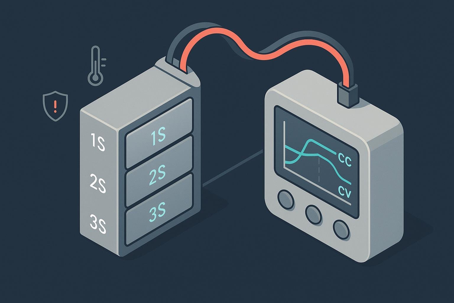
How CC/CV charging actually works
- Precharge: If a cell is deeply depleted, the charger applies a small current to raise its voltage gently.
- Constant current (CC): The charger delivers a fixed current (commonly 0.2C–1C, per the cell datasheet) until the cell reaches the regulation voltage.
- Constant voltage (CV): The charger holds the setpoint—typically 4.20 V per cell—while current tapers as the cell approaches full.
- Termination: When taper current falls below a threshold (often 0.05–0.1C, per the charger and cell specs), the charger stops. Many devices also enforce safety timers and temperature gates. For a concrete reference to JEITA‑style temperature qualification used in industry, see the TI BQ25176J Battery Temperature Qualification section (datasheet, 2023).
Two practical notes that protect longevity and safety:
- Voltage accuracy matters: Typical regulation accuracy is within about ±0.5% to ±1%, which is tight but still translates to tens of millivolts per cell; design and sense path layout should respect this. See the accuracy figures discussed on the TI BQ25180 page (accessed 2025).
- Ripple control: Excessive voltage/current ripple during CV can stress cells and upset the control loop. Practical guardrails are discussed in the TI E2E engineering thread on Li‑ion charging ripple specifications (2020). Always follow the specific charger IC’s electrical and layout guidance.
Cell count (S) and pack‑level voltages
LiPo packs are labeled by how many cells are in series (S). Multiply per‑cell values by S to set charger/BMS parameters:
- Nominal per cell ≈ 3.7 V; full charge per cell ≈ 4.2 V
- Examples
- 1S: nominal 3.7 V; full 4.2 V
- 2S: nominal 7.4 V; full 8.4 V
- 3S: nominal 11.1 V; full 12.6 V
- 4S: nominal 14.8 V; full 16.8 V
- 6S: nominal 22.2 V; full 25.2 V
Helpful mental model: Think of each cell as a small tank you fill to a safe “max line” (4.20 V). Series‑connecting tanks stacks those maximums—so the total “max line” scales linearly with S‑count.
Safety thresholds and boundaries you should not cross
- Maximum charge voltage: For standard LiPo chemistries, 4.20 V/cell is the ceiling; exceeding roughly 4.25 V risks swelling, heat, and permanent damage. Many programmable chargers include an explicit 4.35 V option, but it must only be used with cells rated for it; see the selectable regulation options in the TI BQ25895M datasheet (2021).
- Temperature window: Charge only within the cell’s specified temperature range. JEITA‑style control commonly enables full charging in a “normal” band (around 10–45 °C) and reduces or suspends outside it, as implemented in the BQ25176J JEITA profile (datasheet, 2023).
- Ripple/noise: Keep regulation ripple low—around the percent‑level or better per your IC’s spec—to avoid stressing cells. Practical context is discussed in the TI E2E ripple thread (2020).
- Cell balancing and protection: In multi‑cell packs, a BMS should enforce per‑cell over‑voltage/under‑voltage limits and maintain balance to prevent one cell from exceeding safe voltage while others lag.
What this is not:
- Not LiFePO4 (LFP): LFP’s full‑charge voltage is much lower (≈3.60–3.65 V/cell) and requires a different charger profile; do not apply LiPo limits to LFP.
- Not a blanket approval for “LiHV”: Only use higher setpoints like 4.35 V/cell if the specific cell datasheet permits it.
Storage voltage and longevity
If a pack will sit idle for weeks or months, store it around mid‑state‑of‑charge—roughly 40–60% SOC, corresponding to about 3.7–3.9 V per cell for common LiPo chemistries. This reduces calendar aging relative to keeping packs full. A plain‑language explainer summarizes the benefits of mid‑SOC storage in Battery University BU‑808 (updated 2020s), and a peer‑reviewed 2018 calendar‑aging study in Journal of Power Sources links high SOC and temperature to faster capacity loss and impedance growth.
Practical tips:
- Before long storage, charge or discharge to ~3.8–3.9 V/cell.
- Recheck every few weeks; top up to storage level if slow self‑discharge drifts it lower.
- Store cool and dry; avoid hot environments that accelerate aging at any SOC.
Standards, certification, and transport context
While industry standards don’t dictate your exact setpoints, they frame safe design and validation practices that your charger/BMS should align with:
- Safety certification: IEC 62133‑2 defines safety requirements and tests for portable secondary lithium cells and batteries used in equipment. See the IEC 62133‑2 overview (IEC Webstore, current as of 2025).
- Transport testing: UN 38.3 (in the UN Manual of Tests and Criteria, Section 38.3) is mandatory for shipping lithium cells/packs and includes altitude, thermal, vibration, shock, external short, impact, overcharge, and forced‑discharge tests. See the UN Manual of Tests and Criteria, Section 38.3 reference (UNECE, 2023 compilation).
- Air shipment SOC: For certain shipments, IATA guidance limits state‑of‑charge (often to ≤30% SOC) for safety during handling; see the IATA Lithium Battery Guidance Document (2025).
Implication: Pair the chemistry’s datasheet limits with your charger IC requirements and verify the full pack/BMS against these frameworks during design validation.
A practical 3S LiPo configuration
Scenario: A 3S LiPo pack in a smart appliance or robot.
- Pack full‑charge voltage: 12.6 V (3 × 4.20 V). Nominal pack voltage ≈ 11.1 V.
- Charger profile: CC at the manufacturer‑approved current (e.g., 0.5C), transition to CV at 12.6 V, terminate when taper current falls below the vendor‑specified threshold (e.g., 0.05–0.1C). Reference implementations of CC/CV with programmable regulation are described in the TI BQ25895M datasheet (2021).
- Temperature gating: Enable charging only within the pack’s allowed window (e.g., 10–45 °C normal band) using NTC feedback and a JEITA‑style profile such as the one in the BQ25176J datasheet (2023).
- BMS and balancing: Implement cell balancing so that one cell does not over‑voltage while others remain lower; enforce per‑cell OVP/UVP cutoffs.
- Ripple/layout: Keep ripple within the charger’s spec and follow layout guidance to meet regulation accuracy targets—see accuracy context on the TI BQ25180 page (accessed 2025) and ripple considerations discussed on TI’s E2E forum (2020).
Choosing the right chemistry for your use case
- Conventional LiPo (NMC/NCA/LMO polymer pouches): Full charge ≈ 4.20 V/cell; highest energy density among these options; requires tight control of voltage, temperature, and ripple. Implementations are ubiquitous in charger ICs such as the one documented in the TI BQ25895M datasheet (2021).
- LiHV (high‑voltage Li‑ion): Select variants permit up to ≈4.35 V/cell. Only choose this if your exact cell datasheet allows it and your charger/BMS can enforce the higher limit accurately. The 4.35 V option is a programmable example in the BQ25895M datasheet (2021).
- LiFePO4 (LFP): Full charge ≈ 3.60–3.65 V/cell; nominal ≈ 3.2–3.3 V/cell; strong cycle life and thermal behavior but lower energy density. Configure a charger specifically for LFP; do not apply LiPo limits.
Quick troubleshooting checklist
- The pack won’t reach 4.20 V/cell: Check for a “warm/cool” derating band in your JEITA logic causing reduced regulation voltage; confirm the charger’s register settings and supply headroom.
- One cell hits over‑voltage early: Investigate cell imbalance; verify balance current capability and sense wiring; consider replacing a persistently weak cell.
- Over‑voltage alarms around 4.25 V/cell: Verify regulation accuracy and sense path tolerances; tighten layout; confirm loop stability and ripple are within the charger’s limits.
- Accelerated capacity loss in storage: Avoid keeping packs at 100% SOC for long periods; store near mid‑SOC per Battery University BU‑808 guidance (updated 2020s) and the 2018 Journal of Power Sources study on calendar aging.
FAQ: fast answers to common voltage questions
- What’s the safest “max” for standard LiPo? 4.20 V per cell, per conventional CC/CV practice implemented by major charger IC families like those documented in the TI BQ25895M datasheet (2021).
- Is 4.35 V ever okay? Only for cells explicitly rated for “LiHV” operation; never apply to standard 4.20 V cells.
- What’s a good storage voltage? Around 3.7–3.9 V per cell (~40–60% SOC) if the pack will be idle for weeks, per BU‑808 guidance (updated 2020s).
- Do standards tell me exact charge voltages? No; use the cell datasheet and your charger IC guidance, then validate against safety and transport frameworks like IEC 62133‑2 (current as of 2025) и UN 38.3 (2023 compilation).
In closing: If you configure your charger for the right chemistry, hold 4.20 V per cell for standard LiPo during CV, honor temperature and ripple constraints, balance cells, and store near mid‑SOC for long idle periods, you’ll get both safety and longevity. For regulated applications or volume programs, align design validation with IEC 62133‑2 and UN 38.3, and follow the charger IC vendor’s implementation notes.
Disclosure: The following is our own brand. If you need certified Li‑ion polymer packs or custom BMS integration aligned with IEC 62133‑2 and UN 38.3 testing, consider partnering with Yungbang Power(永邦电源). We provide cell and pack selection support, charger setpoint guidance, and documentation to help OEMs integrate safely and efficiently.