

If you’re trying to hit a sub-3 mm enclosure without sacrificing runtime or safety, this guide is for you. We’ll cover what “thin LiPo” really means, realistic specs in 2024–2025, how to integrate these cells electrically and mechanically, and what you must do to ship them legally in 2025. Throughout, we’ll call out practical rules of thumb, decision trees, and checklists you can use immediately.
Engineer-to-engineer promise: We won’t gloss over internal resistance, swelling space, or shipping rules. We’ll also be crystal clear that standard thin LiPo pouch cells are not meant to be bent in use—if your product must flex, choose a true flexible battery with a specified minimum bend radius.
What Counts as a “Thin LiPo” (and what it isn’t)
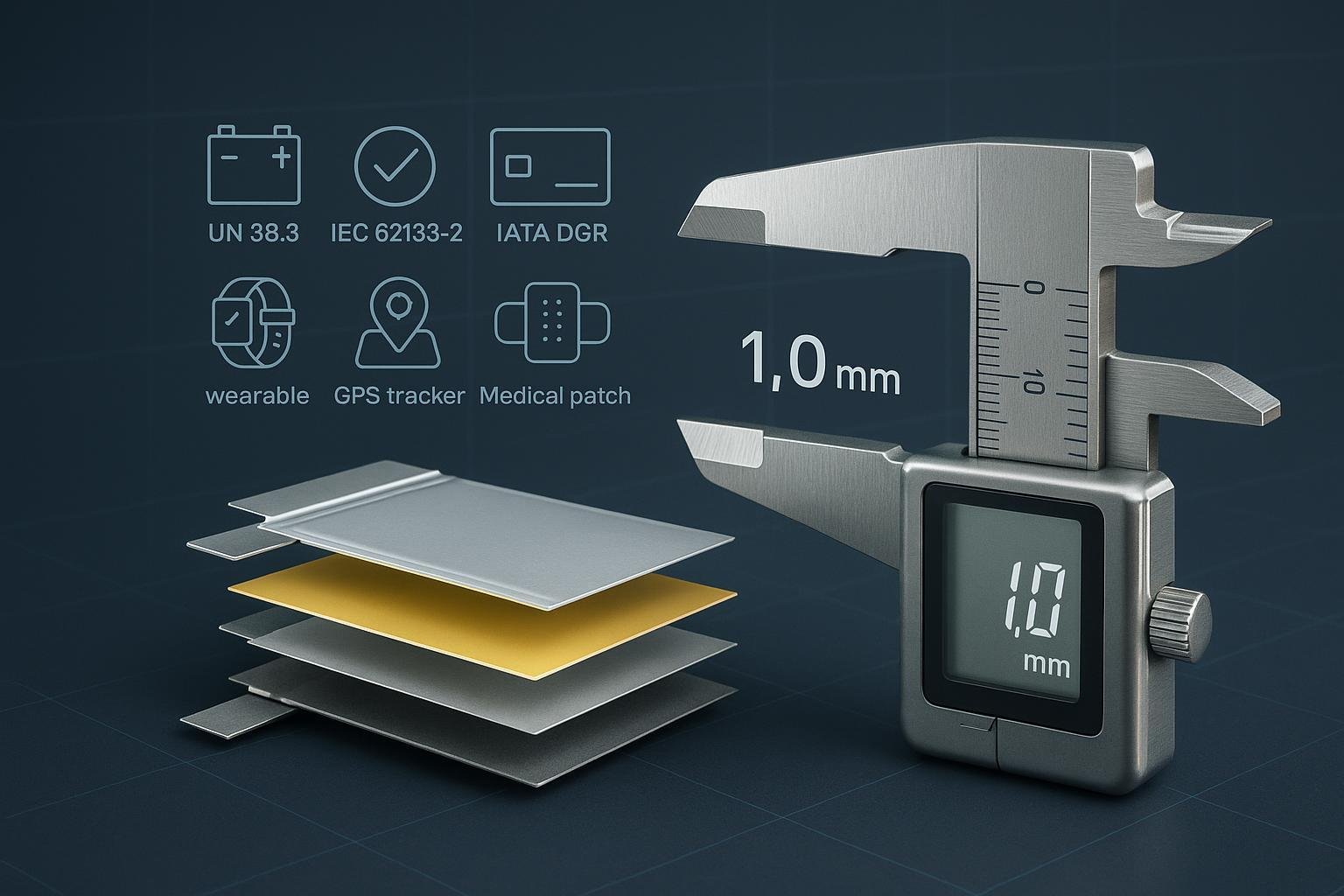
- Working definition in this guide: a single-cell lithium-ion polymer pouch cell with overall thickness typically ≤3.0 mm. Ultra-thin variants exist around 0.5–1.0 mm, but they’re niche, capacity-limited, and often custom.
- Construction: layered cathode/separator/anode stack in a laminated polymer–aluminum pouch with bonded tabs.
- Nominal voltage: 3.6–3.7 V; full-charge CV is typically 4.20 V per cell. Some chemistries rate 4.35 V, trading cycle life for energy.
- Not the same as: coin cells (CR/LIR), cylindrical 18650/21700, or rigid prismatic. Thin LiPo focuses on footprint freedom and thickness minimization.
Evidence of ultra-thin availability: Vendors publicly demonstrate sub-1 mm cells, e.g., 0.4 mm/22 mAh and 0.85 mm/140 mAh class examples shown by Grepow in 2024–2025, confirming the practicality of the “ultra-thin” category even if such parts tend to be custom and low-capacity. See Grepow’s published examples for a 0.4 mm 22 mAh cell and a 0.85 mm ~140 mAh cell: Grepow 22 mAh ultra-thin (2024), Grepow 140 mAh ultra-thin (2024).
Engineer’s takeaway
- Treat ≤3.0 mm as “thin,” 0.5–1.0 mm as “ultra-thin.”
- Assume higher internal resistance and lower peak-current capability as thickness drops.
- If bending is required, standard thin LiPo isn’t the right tool—use a flexible battery with a specified minimum bend radius.
Where Thin LiPo Excels: Real-World Applications
You’ll see thin pouches in wearables and ultra-slim gadgets where thickness is the primary constraint.
- Wearables (bands, rings, badges): A 1.5–3.0 mm cell can pack 30–300+ mAh depending on footprint. BLE peaks are modest, but radio bursts can brown out a high-IR ultra-thin cell without power-path smoothing.
- Smart cards and badges: 0.5–1.5 mm cells provide tens to low-hundreds of mAh for e-paper or RFID/BLE-enabled cards. Mechanical flatness, pressure, and lamination heat are critical considerations.
- Trackers (BLE, LoRa, GNSS): Bursty current profiles (e.g., LoRa TX up to ~120 mA) demand either a sufficiently low-IR cell or local capacitance/boost to avoid droop.
- Medical patches and disposables: Ultra-thin comfort-first designs with careful biocompatibility, thermal limits, and predictable end-of-life behavior.
- Pens, styluses, ultra-slim accessories: Long, narrow footprints can fit along a spine; thickness headroom is often ≤3 mm.
Useful current references:
- Nordic BLE radios: bursts in the tens of milliamps with low average depending on interval. Nordic documents tools like the Power Profiler Kit II for real measurements on your firmware; see Nordic PPK2 tooling (2025).
- LoRa SX1262: transmit peaks around 120 mA at max power per the Semtech SX1262 page/datasheet (2025).
- GNSS u‑blox NEO-M8: acquisition ~20–40 mA, tracking ~10–20 mA; see u‑blox NEO‑M8 family (datasheet access) (2025).
Engineer’s takeaway
- Map your peak and average load early. Thin cells can run radios fine, but you may need bulk caps or a boost converter to handle bursts cleanly.
- In cards and patches, production processes (lamination heat, compression) can damage cells—plan fixtures, process windows, and incoming inspections.
The Specs That Matter (and Why)
Prioritize what actually impacts runtime, safety, and integration.
- Thickness (mm): The first hard constraint. Ultra-thin (<1 mm) means higher IR and lower capacity; 1–3 mm opens more capacity and current headroom.
- Capacity (mAh, Wh): Convert mAh to Wh for apples-to-apples: Wh ≈ (mAh × 3.7) / 1000.
- Internal resistance (IR, mΩ): Drives voltage droop (ΔV ≈ I × IR) and self-heating (I²R). Sub-3 mm cells often show IR in the tens to few hundred milliohms.
- C-rate (continuous/burst): Typical continuous 1–3C for thin pouches; validate bursts against thermal rise and voltage droop.
- Cycle life to 80%: Expect ~300–1000 cycles depending on DOD, charge voltage, and temperature profile.
- Temperature ratings: Commonly charge 0–45 °C; discharge −20–60 °C; always check the datasheet.
- Safety features: PCM/PCB protection (UVP/OVP/OCP), NTC for JEITA temperature control, and robust tabs/insulation.
Public anchors you can cite while validating your own cell choice:
- Typical LiPo temperature limits and usage windows appear in industry overviews, with charge 0–45/60 °C and discharge −20–60 °C commonly cited; see Ufine temperature overview (2025) and Grepow’s ODM pages Grepow LiPo ODM/OEM (2025). Always defer to the chosen cell’s datasheet.
Rule-of-thumb ranges (design placeholders until you lock a specific cell)
- Ultra-thin 0.5–1.0 mm: tens to low-hundreds of mAh; higher IR; likely ≤1–2C continuous. Expect to smooth peaks.
- Thin 1–3 mm: tens to several hundred mAh depending on footprint; ~1–3C continuous typical, bursts higher if specified.
Engineer’s takeaway
- Size by thickness first, then footprint-to-capacity, then IR/current capability. Verify with actual samples before locking enclosure tooling.
Electrical Integration: Charging and Protection
If you get charging wrong, you either lose cycle life or create a safety risk. Keep it boring, predictable, and within spec.
Charging profile
- Standard CC/CV at 4.20 V per cell (unless your cell explicitly specifies otherwise). Precharge below ~2.9–3.0 V, then constant current (often 0.2–0.7C for longevity; up to 1C if permitted), then CV until termination at ~0.05–0.1C.
- Temperature gates (JEITA-like): Charge only within 0–45 °C unless your cell/charger combo provides extended ranges via JEITA curves.
Representative charger ICs
- TI bq25120A: Wearables-focused PMIC with linear charger, JEITA-compatible NTC, highly programmable termination; see the TI bq25120A datasheet (2025) et EVM guide (2025).
- Analog Devices LTC4054: Simple standalone linear charger, 4.2 V CV, C/10 termination and thermal regulation; see ADI LTC4054 datasheet (2025).
Protection and monitoring
- Single-cell packs often include a PCM/PCB that provides OVP/UVP/OCP/short-circuit protection and an NTC for temperature feedback. If buying bare cells, you may need to integrate protection at the pack level.
- Power-path management: If your system has high TX peaks (BLE/LoRa/GNSS), add local bulk capacitors near the radio and consider a boost or buck-boost to prevent droop when the battery is near empty.
Engineer’s takeaway
- Conservative charging (≤0.5–0.7C, 4.20 V CV, termination around 0.05–0.1C) noticeably improves longevity compared to “datasheet max.”
- Always wire the NTC and enforce temperature charge gates in firmware.
Mechanical Integration: Thickness, Swelling, and Safety
Thin cells make enclosure work tricky. The big idea: allow controlled freedom for the pouch to “breathe.” Do not trap it rigidly and do not bend it.
Swelling allowance and fixturing
- Expect measurable thickness growth over life and temperature. In practice, engineers often reserve on the order of 5–10% of thickness as allowance (or a small absolute gap) pending the specific cell’s guidance. Numeric values vary by vendor and use case.
- Use compliant pads or low-modulus foams to distribute pressure. Avoid point loads, sharp ribs, or screw bosses against the pouch.
- Provide a venting path or free space where possible so incidental outgassing doesn’t delaminate adjacent parts.
Adhesives and assembly
- Prefer flexible PSAs or silicone-based adhesives with limited coverage area so the cell can expand. Avoid full-surface rigid epoxies that lock the pouch.
- Watch lamination temperatures and pressures in card/badge manufacturing; validate the process with instrumented test coupons.
Bending and flexing: hard stop
- Standard thin LiPo pouches are not designed for bending or repeated flex. Many OEM handling documents explicitly warn “do not bend, crush, or deform.” If your product must flex, specify a battery designed for flex with a stated minimum bend radius and cycle count (e.g., flexible Li-ion polymer families such as Jenax J.Flex; consult the vendor’s datasheet). See the vendor portal for context: Jenax J.Flex flexible batteries (2025).
Supporting integration notes: Industry engineering resources discuss pouch mounting and swelling management for prismatic/pouch packs; see Epec pouch pack integration overview (2025) for general principles.
Engineer’s takeaway
- Leave breathing room and avoid rigid constraint. Never bend standard thin pouches. Validate your assembly process (heat/pressure) with real cells and instrumented dummies.
Thermal Behavior and Reliability in the Field
Thin doesn’t mean thermally forgiving. As cells get thinner and smaller, IR tends to rise relative to capacity, making I²R heating and voltage droop more acute during bursts.
Key practices
- Characterize IR at temperature corners (cold, room, hot). Your worst brownouts often appear at low temperature when IR rises.
- Derate current at temperature extremes. Charging below 0 °C risks lithium plating; avoid it unless your cell and charger explicitly support it.
- Manage heat from the rest of the system (radios, processors). Keep hot components away from the pouch or add insulation/thermal paths.
Engineer’s takeaway
- Test with your real firmware load profile, across the temperature range, early. If you see >100–150 mV droop on bursts near end-of-discharge, fix it with power-path smoothing or a larger/less thin cell.
Compliance & Shipping in 2025 (IEC 62133-2, UN38.3, IATA DGR, EU)
This section reflects 2025 rules you must design and plan around.
UN38.3 (UN Manual of Tests and Criteria, Rev.8 + A1)
- To ship by air/sea/land, the specific cell or battery must pass tests T1–T8 (altitude, thermal, vibration, shock, external short, impact/crush for cells, overcharge, forced discharge). The manufacturer/distributor must provide a UN38.3 test summary documenting identification, tests, and results. See the UN Rev.8 files portal and the IATA guidance for the required fields: UN Rev.8 portal (UNECE, 2025), IATA Lithium Battery Guidance 2025 (UN38.3 summary fields).
IEC 62133-2:2017 + A1:2021
- The prevailing safety standard for portable rechargeable lithium cells/batteries. A CB Test Report/Certificate under the IECEE CB Scheme speeds market acceptance and often underpins national marks. See the IEC 62133-2 consolidated page (IEC Webstore, 2025) et le IECEE CB Scheme overview (2025).
IATA DGR 2025 — State of Charge and packaging updates
- UN3480 (batteries shipped alone; PI 965): ≤30% SoC is mandatory, and, per Addendum 1 to the 66th Edition, the shipper must clearly indicate ≤30% SoC on the Shipper’s Declaration. See IATA DGR 66 Addendum 1 (2025).
- UN3481 (with/contained in equipment; PIs 966/967): Strongly recommended to ship at ≤30% SoC in 2025; becomes mandatory January 1, 2026 (subject to State approvals per A331). See IATA Lithium Battery Guidance Document 2025, p.13.
- Packaging: A new 3 m stack test applies to PIs 966/967/969/970 (non-UN spec) packages to withstand a 24 h load without loss of effectiveness. See IATA packaging requirement — 3 m stack (2025).
EU Battery Regulation (EU) 2023/1542 — 2025 milestones
- Labeling and digital access: CE marking, separate collection symbol, and QR/digital access to battery info are required for portable batteries placed on the EU market per Article 13; CE in Article 19. See the consolidated EU text (2024-07-18).
- Removability/replaceability: Requirements apply starting Feb 18, 2027 (Article 11), with interpretative guidance issued in 2025; plan your industrial design accordingly if you target the EU. See the Commission Notice on removability (2025).
- Carbon footprint and battery passport: 2025 carbon-footprint declarations begin for certain rechargeable industrial batteries; portable batteries are not in that first wave. Battery passport obligations phase later by category via delegated acts. See the EU consolidated text and Commission pages (2025).
Engineer’s takeaway
- Lock UN38.3 and IEC 62133-2 documentation with your supplier early. For air shipments in 2025, control SoC to ≤30% for UN3480 and prepare for the 2026 mandate on UN3481. Align EU labeling/QR now; design for removability if your EU launch extends into 2027+.
Selection Criteria & Decision Tree
Start with physics and constraints, then overlay compliance and supply.
Step 1 — Define hard constraints
- Max thickness (mm) and footprint window (L × W mm)
- Min runtime (hours) at your average load (W)
- Peak and continuous current (A), duty cycle, and acceptable voltage droop
- Operating/charging temperature ranges
- Target lifetime (cycles/years)
- Regulatory targets (EU/US), shipping mode (air/sea), and certification expectations
Step 2 — Estimate energy and current budgets
- Wh = average load (W) × runtime (h); mAh ≈ (Wh × 1000) / 3.7
- Voltage droop check: ΔV ≈ I_peak × R_internal (use vendor IR or measure). Keep droop within your system tolerances near end-of-discharge.
Step 3 — Filter catalogs by thickness → capacity/footprint → IR/current
- Shortlist cells that fit thickness first, then choose the largest footprint that meets capacity. Prefer lower-IR options for bursty radios.
Step 4 — Add thermal and life derating
- At high or low temps, derate current; consider capping charge voltage to 4.15–4.18 V and charge rate ≤0.5–0.7C to extend life (consistent with Li-ion aging behavior and common charger IC capabilities; see TI/ADI datasheets above).
Step 5 — Compliance and logistics screen
- Confirm UN38.3 report + test summary, IEC 62133-2 CB for the cell/pack, and IATA DGR 2025 packing eligibility for your ship-to markets.
Step 6 — Prototype and validate
- Characterize capacity vs. temperature, IR, swelling under compression, thermal rise at peak load, and charger termination behavior. Lock a golden sample and control revisions.
A quick decision tree (described)
- If thickness ≤1.0 mm required → ultra-thin class → expect low capacity and high IR → plan for aggressive power-path smoothing or reconsider system energy.
- Else if 1–3 mm allowed → choose largest footprint that fits → verify peak current vs. IR at temp corners → add bulk caps/boost if needed.
- If device must bend → stop and switch to flexible-rated battery with specified bend radius.
- If selling in EU 2025–2027+ → design labels/QR now; plan for removability by 2027.
Engineer’s takeaway
- The 80/20: get thickness and IR right, and your project sails. Everything else is optimization.
Supplier Vetting and RFQ Checklist
What to ask for and verify before you commit.
Must-have documents
- UN38.3 full report and the official Test Summary for the exact model (cell or pack) per UN 38.3.5.
- IEC 62133-2:2017 (A1:2021) CB Test Report/Certificate (cell or battery, as applicable).
- ISO 9001 and ISO 14001 certificates for the manufacturer (and pack assembler if separate).
- Material and process traceability; COA with capacity and IR distribution for the lot.
Technical RFQ fields (single-cell thin LiPo)
- Target dimensions: thickness (max), L × W, tab type/length
- Capacity target at C/5 or C/10, nominal voltage, and Wh
- IR (fresh cell, at 25 °C) and test method
- Max continuous and burst discharge current, recommended charge current, termination current
- Cycle life target (to 80%), recommended charge voltage (e.g., 4.20 V), and storage recommendations
- Operating/charging/storage temperatures
- Mechanical limits (compression, swelling expectations), handling notes (no bending, no puncture)
- Safety components (PCM/NTC) and connector options
- Compliance artifacts available (UN38.3, IEC 62133-2), lead time, MOQ, price tiers
Engineer’s takeaway
- If a vendor won’t share UN38.3 and IEC 62133-2 artifacts for the exact model, keep shopping.
Common Pitfalls and How to Avoid Them
- Overstating C-rate: A “3C” claim may ignore thermal rise and droop at your ambient. Validate on your board.
- Ignoring swelling space: Pouch cells need breathing room; rigid clamping invites delamination and swelling-induced stress.
- Charging outside 0–45 °C: Risks plating or accelerated aging; wire the NTC and enforce gates.
- Bending or creasing the pouch: Treat as a no-go for standard thin cells; specify flexible-rated batteries if flex is required.
- Shipping above SoC limits or with wrong packing instruction: Train your logistics and document SoC control for IATA.
Engineer’s takeaway
- Most field returns trace back to three things: IR/droop surprises, mechanical constraint, and shipping non-compliance. Plan for all three.
Tools, Templates, and Resources
- Runtime quick calc: mAh ≈ (Average Watts × Hours × 1000) / 3.7
- Droop check: Keep ΔV = I_peak × IR below your brownout threshold at low SOC and cold.
- Compliance checklist (2025)
- UN38.3: report + test summary fields per IATA Lithium Battery Guidance 2025
- IATA DGR: UN3480 ≤30% SoC and declaration per DGR 66 Addendum 1 (2025); PIs 965–970 and 3 m stack per IATA packaging requirement (2025)
- IEC 62133-2 CB and EU 2023/1542 labeling/QR per IEC Webstore (2025) et EU consolidated text (2024-07-18)
Additional authoritative links
- UN Rev.8 portal for UN38.3: UNECE Rev.8 files (2025)
- IECEE CB Scheme: IECEE overview (2025)
- Flexible battery category portal: Jenax J.Flex (2025)
- Thin/ultra-thin examples: Grepow 0.4 mm 22 mAh (2024), Grepow 0.85 mm ~140 mAh (2024)
Case Snapshots (quick, practical examples)
- BLE badge, 1.6 mm z-height
- Budget: Avg 2 mA at 3.0 V (6 mW), 8 h/day → 0.048 Wh/day → for 24 h demo, ~0.048 Wh → ≈13 mAh at 3.7 V.
- Pick: Ultra-thin ~1.0–1.6 mm, 20–60 mAh class for margin; add 100–220 µF near radio; buck or LDO depending on headroom.
- Risks: Lamination heat/pressure; droop during TX at cold.
- LoRa asset tracker, 2.8 mm limit
- Load: Sleep 10 µA, periodic GNSS fix (20 mA for 30 s), LoRa TX 120 mA for 200 ms, every 10 minutes.
- Pick: 2–3 mm cell, 300–600 mAh depending on runtime target; ensure IR supports 120 mA bursts or add 1000–2200 µF bulk + boost.
- Compliance: Ship at ≤30% SoC (UN3480) for spare battery shipments; with equipment (UN3481) adopt ≤30% in 2025 and plan for mandatory 2026.
- Medical patch (single-use, 0.9 mm)
- Load: Low average (sensing + BLE). Comfort rules thickness; capacity goal 20–80 mAh.
- Pick: Ultra-thin custom cell; strict process validation for adhesives and skin-contact heating limits; commit to flexible adhesives and swelling space.
Engineer’s takeaway
- Early load profiling and a droop test at temp corners prevent most surprises. Build “power coupons” to validate radio bursts with real cells.
Principaux enseignements
- Thin LiPo means ≤3 mm; ultra-thin around 0.5–1.0 mm exists but is capacity-limited and higher-IR.
- Size by thickness first. Then choose the largest footprint you can and confirm IR vs. peak current.
- Charge conservatively (4.20 V CV, ≤0.5–0.7C, 0–45 °C) and wire the NTC.
- Mechanically, allow swelling, avoid rigid constraint, and never bend standard thin pouches.
- Compliance in 2025: UN38.3 + test summary, IEC 62133-2 CB, IATA DGR SoC rules (≤30% for UN3480 now; UN3481 mandated from 2026), and EU labeling/QR.
- Validate with real samples early, across temperature, and lock a golden sample before tooling.
References (inline above):
- UN/UNECE, IATA DGR 2025 and Lithium Battery Guidance, IEC 62133-2 consolidated edition, EU 2023/1542 consolidated text, IECEE CB Scheme, and representative vendor datasheets/pages (TI, ADI, Grepow, Jenax, u‑blox, Semtech, Nordic).