

If you fly FPV, build RC models, or design portable electronics, you’ve seen bold labels like “75C” or “150C” on LiPo packs. What do those numbers really mean—and how should they influence your choices? This guide demystifies C‑rate with practical math, real test conditions, and safety context so you can size and use packs confidently.
What “C‑rate” actually means (in one minute)
C‑rate is the charge or discharge current expressed as a multiple of a battery’s capacity in amp‑hours (Ah). At 1C, current equals capacity (a 2.2 Ah pack at 1C = 2.2 A). As a quick rule, steady‑current runtime is roughly 1/C hours. See the concise definition in Battery University: What is C‑rate.
- Formula: C = I / Ah → I = C × Ah
- Example: A 2.2 Ah LiPo labeled “30C” theoretically implies 30 × 2.2 = 66 A. Whether it can truly sustain 66 A depends on temperature, voltage cut‑off, and how the pack was built and tested.
- Charge vs discharge: The same “C” notation is used for charging, but recommended charge C‑rates are usually much lower than discharge rates to preserve life.
Think of C‑rate as how wide you open the “current valve” relative to the tank’s size. Open it too wide for too long and you’ll get severe voltage sag and heat.
Why C‑rate matters: voltage sag, heat, and usable capacity
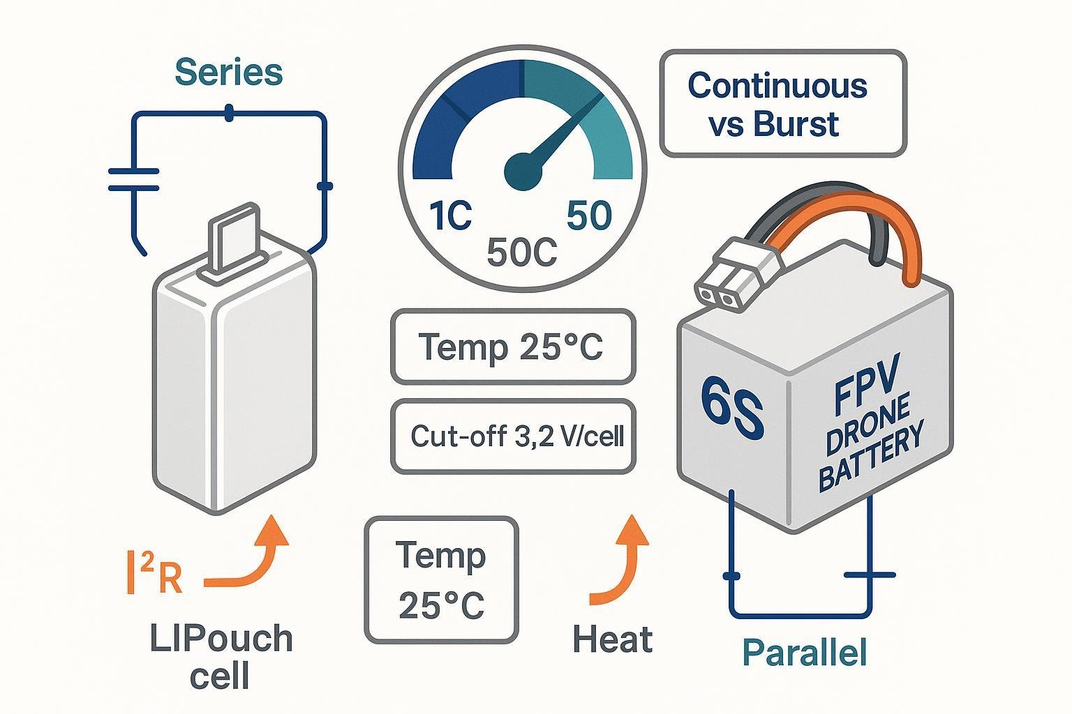
At higher C‑rates, internal resistance causes more voltage drop (ΔV ≈ I × R) and more heat (P ≈ I² × R). As rate and temperature interplay, available capacity at high load declines due to polarization and transport limits. For a deeper look at these mechanisms and typical discharge behavior, see Battery University: Discharge characteristics of Li‑ion.
What you’ll observe in practice:
- Punch vs brownouts: High‑C packs with low internal resistance hold voltage better during throttle punches, reducing ESC brownouts.
- Heat compounding: The hotter the cells, the higher the resistance rise over time; heat accelerates aging.
- Shorter usable capacity at high load: Your “1500 mAh” pack won’t deliver 1.5 Ah at a very high constant C—rate capability limits and thermal throttling reduce what you can practically extract while staying within safe limits.
Continuous vs burst (peak) C‑ratings—what’s real and what’s marketing
Not all “C” numbers are equal. Two terms you’ll see:
- Continuous C‑rating: The maximum current the cell/pack can deliver indefinitely under specified conditions without exceeding temperature or voltage limits. Reputable datasheets state conditions. For instance, the Molicel P45B cell is specified at 45 A continuous with an 80 °C cutoff and 2.5 V discharge cut‑off per cell in the Molicel P45B datasheet, rev 1.2.
- Burst (peak) C‑rating: A short‑duration current (seconds) the pack can supply without immediate damage. Duration is not standardized across the hobby market, and public product pages often omit the test time and conditions. Example: a Tattu R‑Line 6S pack advertises “150C” and “max 260C,” but the page provides no burst duration in its public specs—illustrating why you should treat such claims cautiously (Tattu R‑Line 6S 150C product page).
How to read C‑ratings critically:
- Favor continuous current tied to explicit conditions (ambient/cell temperature, discharge cut‑off voltage, and allowable temperature rise or limit).
- If “burst” is listed, look for the exact duration (e.g., 5–10 s) and the duty cycle. If it’s not stated, assume marketing inflation and rely on conservative margins.
Test conditions define C‑rate in the real world
Performance specs depend on how they’re measured. The IEC 61960 series provides standardized methods to test portable Li‑ion cell capacity and rate performance with defined temperatures, currents, and cut‑offs; see the IEC 61960‑4:2020 performance test methods page.
Key conditions to check in any datasheet:
- Temperature: Many specs are at 20–25 °C. Colder cells have less power; hotter cells age faster.
- Discharge cut‑off voltage per cell: This defines when the test stops (e.g., 2.5 V per cell for some cylindrical power cells; pouch LiPos may specify different values).
- Allowable temperature rise or absolute limit: Some documents specify “stop at 80 °C cell temperature.”
- Rest periods and state of charge (SOC): Pulse tests often specify initial SOC and rest intervals.
Temperature and cutoff policy: the two levers that change everything
Cold reduces power capability and increases voltage sag; heat enables higher instantaneous power but accelerates aging and safety risk. Practical guidance aligns with lab observations summarized in Battery University: Discharging at high and low temperatures.
- Cold‑weather flying: Expect reduced punch and earlier voltage sag. Warm packs to room temperature before demanding flights.
- Hot environments: Aggressive throttle in high ambient temps can push cells toward thermal limits; manage airflow and avoid sustained peaks.
- Cut‑off strategy: Engineering tests define a per‑cell cut‑off (e.g., 2.5–3.0 V) under controlled conditions; pilots and device designers typically set higher in‑use thresholds to retain margin and protect cycle life.
How C‑rate scales in series and parallel packs
- Series (S): Voltages add; current through each series cell is the same. The pack’s C‑rating does not change by adding cells in series—only voltage increases. See the overview in Battery University: Series and parallel configurations.
- Parallel (P): Capacities (Ah) add; at the same C‑rate, the allowable pack current increases proportionally to total capacity. Current should share evenly across parallels; mismatched cells, wiring, or thermal gradients can limit real capability.
Worked examples:
- 3S2P from 2.0 Ah cells rated 20C continuous → total capacity 4.0 Ah; at 20C, pack current capability ≈ 80 A (assuming good current sharing and cooling).
- 6S 1300 mAh FPV quad: Cruise 35–45 A with bursts to 80 A. Continuous C demand at cruise ≈ 27–35C; size the pack/system so cruise is well within a validated continuous spec (don’t rely only on a “150C” label without test conditions). Match connectors and wiring to the same current.
Safety and standards: what they do—and don’t—cover
Safety and performance standards give you guardrails, but they do not define marketing “burst C.”
- Portable Li‑ion safety (cells and batteries): The widely used framework is IEC 62133‑2:2017 with Amendment 1:2020, which specifies safety tests such as external short‑circuit, overcharge, forced discharge, mechanical, and environmental conditions; see the IEC 62133‑2 page.
- Battery packs for consumer/commercial products: UL 2054 (current edition 2020) covers pack‑level construction and tests like overcurrent and short‑circuit; see the UL 2054 standard scope page.
- Lithium cells safety tests: UL 1642 (2020) specifies cell‑level abuse tests including short‑circuit and thermal; see the UL 1642 scope.
- Automotive/performance cells: IEC 62660‑2:2018 defines performance tests (including rate capability) for vehicle cells with specific temperatures and voltages; see the IEC 62660‑2 page.
- Performance test methods for portable cells: The IEC 61960 series (e.g., 61960‑4:2020) provides standardized methods to measure capacity and rate performance under defined conditions; see the IEC 61960‑4 overview.
Takeaway: Use these standards to understand safety expectations and test methods, but evaluate any pack’s “C” claims against its own datasheet conditions and third‑party measurements when available.
Choosing the right C‑rating: a step‑by‑step, 2025‑ready checklist
- Characterize your load.
- RC/FPV: Log current in flight (OSD/current sensor) or bench‑test with a wattmeter.
- Consumer electronics: Use a bench supply and shunt to capture steady and peak draw.
- Translate to C.
- Required continuous C ≈ I_continuous / Ah; peak C ≈ I_peak / Ah.
- Add margin.
- Target normal operation at roughly 60–80% of a validated continuous capability. Treat “burst” as seconds only, not for sustained climbs or prolonged tool loads.
- Check datasheet conditions.
- Prefer cells/packs that state ambient/cell temperature, per‑cell cut‑off voltage, and thermal limits (e.g., “stop at 80 °C”). The Molicel P45B datasheet is a good example of explicit conditions.
- Verify the rest of the system.
- Ensure connectors (e.g., XT60/90), wires, and ESCs can carry the same current with acceptable temperature rise and voltage drop.
- Validate with measurements.
- Measure internal resistance (DC or AC) and observe voltage sag under a known load. Log pack temperature during representative use; retire packs that swell or run hot at modest loads.
- Charge conservatively unless proven otherwise.
- Many lithium‑based packs fare better at 0.5–1C charge unless the datasheet grants higher; elevated temperature and aggressive charging accelerate aging, as summarized in Battery University: How to prolong lithium‑based batteries.
- Manage temperature.
- Avoid sustained operation that pushes cell temps past ~60–70 °C; provide airflow in drones and robust thermal paths in devices.
Practical FAQs and myth‑busting
- Is a higher C‑rating always better?
- Not necessarily. True high‑C packs often weigh more (more electrode mass, thicker tabs) and may sacrifice energy density. Choose enough C to meet your load with margin; chasing labels can add weight without real benefit.
- Do series cells increase C‑rating?
- No. Series increases voltage; the allowable current per series string stays the same. Parallel increases capacity and total allowable current. See Battery University: Series and parallel configurations.
- Why do packs “puff” after hard use?
- Excess heat and high C‑rates accelerate side reactions that generate gas and increase internal resistance; sustained abuse shortens life. Managing C‑rate and temperature reduces this risk, consistent with trends discussed in Battery University: Discharging at high and low temperatures.
- Are “burst” labels standardized?
- No. There is no universal hobby standard that defines “burst duration.” Unless a vendor specifies exact timing and conditions (rare on public product pages like the Tattu R‑Line 6S 150C page), regard burst claims as marketing and size for continuous needs.
- What about product certifications—do they guarantee honest C‑ratings?
- Safety certifications (e.g., IEC 62133‑2:2017+A1:2020; UL 2054; UL 1642) indicate a product passed defined safety tests, not that its marketing C‑label has a standardized meaning. See IEC 62133‑2, UL 2054 scopeet UL 1642 scope.
The bottom line
- C‑rate is a simple ratio with complex consequences. It determines how hard you can push a pack before voltage sags and heat accelerates wear.
- Trust continuous ratings tied to explicit conditions, be skeptical of undefined “burst,” and size with margin.
- Understand your configuration: series raises voltage; parallel raises allowable current.
- Keep temperature and charge rate in check to protect performance and cycle life, per best‑practice principles summarized by Université de la batterie and standardized performance methods like IEC 61960‑4:2020.
With these fundamentals, you can choose, integrate, and care for LiPo packs for RC/drones and consumer electronics with confidence and safety—without being misled by a single big “C” number.