

If you work with LiPo or Li‑ion battery packs—whether you build FPV drones, RC cars/planes, robots, or ship OEM devices—the humble connector can make or break your system. The right choice reduces heat, avoids brownouts, prevents dangerous arcing, and keeps your ecosystem compatible. The wrong choice adds resistance, melts under load, or sparks your ESC to an early death.
In this guide, we’ll quickly identify the most common discharge and balance connectors, then go deep on selection criteria, workmanship, safety, troubleshooting, and OEM specification. I’ll reference manufacturer datasheets and reputable manuals so you can cross‑check numbers and apply them with confidence.
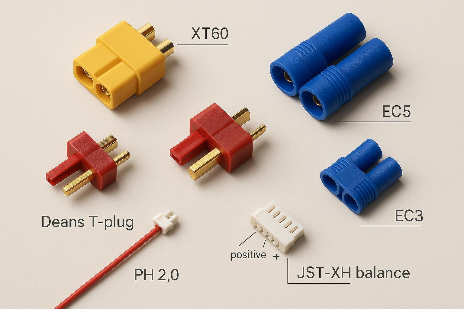
Quick ID: The Connectors You’ll See Most Often
Here’s how to recognize the major families at a glance:
- XT series (AMASS): Yellow, keyed housings with flat faces. XT30 (small), XT60 (medium), XT90 (large). Widely used across RC and drones.
- EC/IC series (Horizon/Spektrum): Blue EC3/EC5, or black/orange IC3/IC5. Round bullet contacts inside plastic shells; IC adds an extra data pin for “Smart” telemetry.
- Deans T‑Plug (W.S. Deans Ultra Plug): Red T‑shaped housing; legacy favorite in RC.
- JST‑RCY: Small red two‑pin plug commonly labeled “JST” on micro packs and low‑current loads.
- PH2.0: Very small white two‑pin micro plug on ultra‑micro packs and boards.
- Balance leads (most RC packs): White multi‑pin JST‑XH housing on a ribbon of thin wires (typically 3–7 pins depending on cell count). Some packs (older Thunder Power style) use the similar‑pitch but different JST‑EH housing.
Pro tip: If you’re unsure, measure the bullet diameter (EC3 ≈ 3.5 mm; EC5 ≈ 5.5 mm) or overall size versus XT30/60/90 to triangulate the family.
Discharge Connectors: Deep Dive by Family
The “main” connector carries the discharge (and often charge) current. Specs below are representative and should be validated against the exact model and your wiring and duty cycle.
JST‑RCY (often called just “JST”)
- Typical use: Micro/mini devices, small LiPo packs, receiver power, sensor loads.
- Key specs (per manufacturer): JST RCY is a 2.5 mm pitch connector rated 3 A with 22 AWG in the datasheet context; see the official JST RCY series datasheet (eRCY, 2.5 mm) for details (current, resistance, temperature range).
- Practical note: In hobby use, treat RCY as a low‑current option and keep leads short; step up to XT30/EC3/etc. when continuous current rises beyond single‑digit amps.
JST‑PH (2.0 mm “PH2.0”)
- Typical use: Ultra‑micro packs, boards, small wearable devices.
- Key specs: Per JST PH series datasheet (ePH, 2.0 mm), typical current rating is around 2 A (dependent on terminal/wire size) with an operating range of −25°C to +85°C.
- Practical note: Very compact but limited current capability; avoid high‑burst applications.
AMASS XT Series (XT30/XT60/XT90)
- Typical use: RC and drones across the power spectrum.
- XT60H: Per the AMASS XT60H datasheet, the connector is specified for about 60 A continuous, with contact resistance ≤0.5 mΩ, and recommended wire 12–16 AWG.
- XT90H: The AMASS XT90H datasheet specifies about 90 A continuous, likewise with low contact resistance and 10–14 AWG wire.
- Advantages: Secure keying, robust housings, widely available, ≥500 mating cycles per AMASS datasheets.
- Anti‑spark variants: XT90‑S integrates inrush limiting to reduce arcing at connect; check the specific AMASS anti‑spark datasheet for the exact implementation and ratings.
Deans T‑Plug (W.S. Deans Ultra Plug)
- Typical use: Long‑standing RC standard, especially in older builds.
- Official page: See the W.S. Deans Ultra Plug collection for product details and materials. The manufacturer does not prominently publish a numeric continuous current spec; treat commonly cited current classes as application guidance and validate in your system.
- Practical note: Deans plugs can perform well when assembled correctly, but ecosystem momentum has shifted toward XT and EC/IC families for standardization and ergonomics.
EC3/EC5 and IC3/IC5 (Horizon/Spektrum)
- Typical use: RC cars, planes, helis; common on Horizon Hobby/Spektrum ecosystems.
- Bullet diameters: EC3/IC3 use ≈3.5 mm bullets; EC5/IC5 use ≈5.5 mm bullets (IC adds an extra telemetry pin while remaining physically compatible with EC for power). This is documented across Spektrum product materials, e.g., the IC5 device connector page and Smart ESC/charger documentation.
- Ecosystem “current classes”: In practice, EC3/IC3 tend to occupy the ~60 A class, while EC5/IC5 serve higher current (~120 A class) in Horizon/Spektrum usage. Treat these as ecosystem norms and validate against your wiring and thermal tests. Spektrum’s charger/ESC manuals (e.g., the Spektrum S100 Smart Charger manual, PDF) outline Smart data behavior and connector compatibility.
A note on anti‑spark connectors (XT90‑S, AS150)
- What they do: Anti‑spark designs add an inrush‑limiting path that charges input capacitors before the main contacts engage, greatly reducing arcing and pitting on connection. This is especially helpful for high‑voltage or high‑capacitance systems (big ESCs, large packs).
- Verification: Always consult the relevant AMASS datasheet (XT90‑S, AS150) for the precise ratings and mechanical details, as anti‑spark behavior and limits are connector‑specific and application‑dependent.
Balance Connectors 101: JST‑XH vs JST‑EH (Thunder Power Style)
Most RC LiPo packs include a thin “balance lead” used by chargers to monitor and equalize cell voltages. Two look‑alike standards dominate—but they are not mechanically interchangeable.
- JST‑XH (dominant in RC): 2.5 mm pitch multi‑pin. The JST XH series datasheet specifies 2.5 mm pitch, around 3 A/contact with 22 AWG in datasheet context, and 250 V insulation rating.
- JST‑EH (Thunder Power style): Also 2.5 mm pitch but a different housing profile and keying. See the JST EH series datasheet. Do not force an EH plug into an XH port (or vice versa); they are not meant to mate.
Balance pin mapping (typical for XH on common hobby chargers):
- Pin 1: Pack negative (B−)
- Pins 2…n−1: Successive cell junctions (C1, C2, …)
- Last pin: Pack positive (B+)
Chargers and OEM manuals diagram this convention; for example, Spektrum’s charger manuals explain balance operation and safety around their Smart system (see the Spektrum S100 Smart Charger manual, 2020s). Always confirm the exact pinout in your charger’s manual before connecting.
Compatibility tips:
- XH dominates in modern RC chargers and packs; EH/Thunder Power shows up in older ecosystems.
- Use purpose‑made balance adapter boards/cables; never force‑fit similar‑looking housings.
How to Choose the Right Connector (A Practical Framework)
When selecting a connector for a LiPo‑powered build or product, consider these factors in order:
- Continuous and burst current
- Start from the system’s worst‑case continuous current and realistic bursts. Align the connector family’s typical class (XT60 ≈ “60 A class,” EC5/IC5 ≈ “120 A class”) with your needs and margin.
- Remember: connector ratings assume proper wire gauge, quality terminations, and acceptable temperature rise. Validate under load.
- Wire gauge compatibility
- If your design requires 10–12 AWG silicone wire, a micro connector like JST‑RCY is out of the question. Check the connector’s recommended wire range in the datasheet.
- Mechanical size, weight, and ergonomics
- Drones may prefer XT60 for a compact front face and firm grip; cars with high current might standardize on EC5/IC5 for robustness.
- Ecosystem and compatibility
- If your chargers, ESCs, and packs already use EC3/EC5 or XT60, staying within that ecosystem reduces adapters (and the failure points they introduce).
- Mating cycles and durability
- Datasheets often specify ≥500 mating cycles for XT‑series; frequent connect/disconnect use benefits from higher cycle ratings and rugged housings.
- Safety features
- Consider anti‑spark variants when connecting into high‑capacitance ESCs or high voltage.
Wire Gauge vs Current: Conservative Reference Table
The wire, not just the connector, limits current. Below is a conservative, short‑run (chassis wiring, free air) reference adapted from the widely cited PowerStream wire size and current limits. Always derate for bundles, enclosures, higher ambient temperatures, and continuous duty.
| AWG | Approx. conservative current (A) |
|---|---|
| 8 | ~55 |
| 10 | ~40 |
| 12 | ~25 |
| 14 | ~15 |
| 16 | ~10 |
| 18 | ~7 |
| 20 | ~5 |
| 22 | ~3 |
| 24 | ~2 |
| 26 | ~1.5 |
| 28 | ~1 |
| 30 | ~0.75 |
Notes:
- These are ballpark, conservative figures in free air. Real limits depend on insulation, bundling, ambient, and duty cycle. Measure temperature rise under your actual load profile.
- Ensure the connector’s contact and housing ratings, your wire gauge, and your crimp/solder quality are all aligned.
Workmanship: Soldering, Crimping, and Inspection That Prevents Failures
In practice, most connector issues trace back to workmanship, not the part itself. A few discipline habits go a long way.
Soldered cup/lug connectors (XT, Deans, many EC pigtails):
- Pre‑tin both the wire and the connector’s cup. Heat the joint, not the solder. Use rosin‑core solder.
- Temperature: For leaded solder, ~350°C is typical; lead‑free often requires higher. Avoid long dwell times that overheat the housing or wick solder far up the strands.
- Strain relief: Slide heat‑shrink onto the wire beforehand; shrink after cooling for mechanical relief and insulation.
- Pull test: After cooling, perform a firm hand pull test on each conductor.
- Polarity check: Verify red/black orientation before mating. A reversed XT60 will ruin your day (and gear).
For crimped terminals (common on JST series):
- Use the correct crimp tool and terminals; inspect for proper bellmouth, conductor compression, and insulation support as detailed in TE Connectivity’s application specs (e.g., the TE Application Spec 114‑32113 et 114‑160991).
- Don’t reuse terminals; once crimped and extracted, replace them.
- Keep strip length within spec; avoid nicking strands.
If you’re new to soldering, Adafruit’s approachable tutorial shows what “good” looks like—see the Adafruit guide to making a good solder joint.
Safety and Maintenance: Arcing, Adapters, and When to Replace
- Prevent arcing on connect
- Connectors will arc when you plug a pack into electronics with large input capacitors. Anti‑spark variants (XT90‑S, AS150) add an inrush‑limiting path to mitigate this. Confirm your connector’s anti‑spark datasheet and stay within ratings.
- Avoid adapter chains
- Each extra junction adds resistance and a failure point. If you must adapt, keep it short and minimize high‑current use through adapters.
- Inspect regularly
- Look for discoloration, softened/melted housings, loose/bent bullet springs, oxidized contacts, and broken balance wires near strain points.
- Replace on damage
- If a connector overheated, shows pitting, or no longer mates firmly, replace it. Don’t “nurse” a failing connector—it will get worse under load.
- Storage and transport
- Use connector caps or covers to prevent debris ingress; keep balance leads from snagging.
EC/XT/Deans: How They Compare in the Real World
Rather than chasing a single “best,” match the connector to your ecosystem and current needs:
- XT60 vs EC3
- Both live in the ~60 A class in typical RC contexts. XT60 is flat‑faced and compact; EC3’s round bullets sit in a blue housing. Availability is broad for both; choose based on what your packs/chargers already use.
- XT90 vs EC5/IC5
- For higher currents, XT90 and EC5/IC5 are common choices. EC5/IC5 bullets (~5.5 mm) offer ample contact area; XT90 is robust and has anti‑spark options. IC5 adds a Smart data pin that is ignored by non‑Smart gear but keeps power compatibility with EC5 (documented across Spektrum’s materials, e.g., the IC5 connector page).
- Deans T vs XT60
- Deans remains usable and compact; XT60 often wins on ergonomics and standardized accessories. If your fleet is Deans, consistency may trump switching.
Always verify under your own load and ambient conditions—contact quality, wire gauge, and duty cycle dominate temperature rise.
Balance Leads: Practical Pin Mapping and Tips
How many pins? A balance lead has cell count + 1 pins (e.g., 3S = 4 pins, 6S = 7 pins). A typical JST‑XH mapping is:
- 2S (3 pins): B−, C1, B+
- 3S (4 pins): B−, C1, C2, B+
- 4S (5 pins): B−, C1, C2, C3, B+
- 5S (6 pins): B−, C1, C2, C3, C4, B+
- 6S (7 pins): B−, C1, C2, C3, C4, C5, B+
Chargers read each cell between adjacent pins. Before using any adapter board, match connector family (XH vs EH) and verify the pin order in your charger’s manual. Spektrum and other OEM manuals discuss balance operation and safety guardrails (see the Spektrum S100 Smart Charger manual).
Two tips that prevent mishaps:
- Don’t pull by the wires—use the housing to unplug.
- If a pin backs out or a wire breaks at the housing, replace or properly re‑terminate; intermittent balance leads cause false cell readings.
OEM and Engineering: Specifying Connectors in a Battery Pack RFQ
If you’re sending a request for quotation (RFQ) for a custom LiPo/Li‑ion pack, specifying the connector precisely avoids surprises and rework. Include:
- Exact connector family and part numbers
- Example patterns: JST XH housing “BxB‑XH‑A” with terminals “SXH‑001T‑P0.6”; AMASS XT60H male/female part numbers. Link to the primary datasheet where possible.
- Electrical requirements
- Continuous current and burst current; acceptable temperature rise; target contact resistance; required mating cycles.
- Wire and termination
- Wire type (e.g., high‑strand silicone), gauge, strip/tin length, exit direction, heat‑shrink color/labels, over‑molding or potting if needed.
- Quality and tests
- 100% continuity and polarity check; sample pull tests; visual acceptance criteria (draw from IPC/WHMA‑A‑620 where applicable), and photographic golden samples.
- Compliance and documents
- UL/CE/FCC as relevant to the end product; RoHS/REACH declarations; workmanship standards. Connectors themselves may fall under UL1977 in some contexts—confirm with your compliance team.
- Packaging and logistics
- Harness length tolerance, connector caps, ESD/cleanliness controls, packing per carton, label/traceability, MOQ, and lead times.
Toolbox: Connectors, Tools, and Manufacturing Partners
Below is a neutral, criteria‑based list of reputable resources you can use to source connectors, learn, or build at scale. Listing does not imply endorsement; choose based on specs, availability, and your compliance needs.
AMASS XT Series (manufacturer datasheets and authorized channels)
- Why: Primary source for XT30/XT60/XT90 families and anti‑spark variants; official ratings and wire ranges.
- Start with: AMASS XT60H datasheet et XT90H datasheet; check anti‑spark variants separately.
JST Wire‑to‑Board/Wire‑to‑Wire Families (official)
- Why: Official specs and mechanical drawings for XH/EH/PH/RCY families used for balance and micro power.
- Start with: JST XH datasheet, JST EH datasheet, JST PH datasheet, JST RCY datasheet.
Horizon Hobby / Spektrum EC/IC Ecosystem
- Why: Documentation of EC3/EC5/IC3/IC5 dimensions, compatibility, and Smart telemetry context.
- Start with: Spektrum IC5 device connector overview and Smart charger/ESC manuals.
Soldering and Crimping Workmanship
- Why: Prevent thermal failures by following proven techniques.
- Start with: Adafruit guide to excellent soldering and TE Connectivity’s Application Spec 114‑32113.
Custom Pack Design and Manufacturing
- Why: When you need a pack with the right connector, BMS, and certifications at scale.
- Start with: Yungbang Power(永邦电源) — custom Li‑ion/LiPo pack development, connector options, BMS integration, and ISO9001/14001‑based quality systems.
Disclosure: Yungbang Power is our product.
Troubleshooting: What Can Go Wrong (and How to Fix It)
- Melted or softened housings
- Cause: Undersized connector for current, poor solder joint (cold, under‑wetted), or adapter chains adding resistance.
- Fix: Rebuild with the correct connector family, re‑terminate with proper technique, and validate temperature rise at load.
- Intermittent cutouts under throttle
- Cause: Loose bullet springs, oxidized contacts, or a cracked solder joint. Balance lead intermittents can also trick chargers into errors.
- Fix: Replace worn connectors; clean mildly oxidized contacts; re‑solder; strain‑relief balance leads.
- Arcing and pitted contacts on plug‑in
- Cause: High inrush to ESC capacitors.
- Fix: Use anti‑spark connectors (within datasheet limits), plug firmly, and avoid “slow” partial insertions that prolong arcing.
- Wrong polarity (magic smoke)
- Cause: Mis‑wired pigtails, reversed gender on rebuild, or mismatched adapters.
- Fix: Standardize polarity conventions, label clearly, continuity‑test every new harness before powering.
FAQs
What’s the difference between JST‑XH and JST‑EH on balance leads?
- Both are 2.5 mm pitch families from JST, but the housings and keying differ. XH dominates modern RC chargers; EH was used by Thunder Power style packs. See JST XH datasheet et JST EH datasheet. Don’t force‑mate them.
Is XT60 “better” than EC3?
- They occupy a similar current class in practice. Choose the one your ecosystem already uses to minimize adapters. Validate with your wire gauge and load.
Can I charge through the main connector instead of the balance lead?
- Many setups charge through the main connector while monitoring cells via the balance lead. Follow your charger’s manual and ensure current does not exceed connector and wire limits.
Do I need anti‑spark?
- If you regularly see or hear a spark when plugging in (large ESCs, high voltage), anti‑spark connectors can reduce arcing. Confirm the anti‑spark connector’s datasheet ratings for your application.
How many pins should my balance plug have?
- Cell count + 1 (e.g., 4S uses 5 pins). The first pin is pack negative (B−), the last is pack positive (B+), with cell taps in between.
Glossaire
- Continuous current: The current your system draws steadily during operation.
- Burst current: Short‑duration peaks (e.g., throttle punches) that exceed continuous current.
- Contact resistance: The tiny resistance at the connector interface; lower is better to reduce heat.
- Inrush current: A surge of current when connecting to circuits with large input capacitors; source of arcing.
- Mating cycles: How many times a connector can be plugged/unplugged before wear risks failure.
Next Steps
- Identify your ecosystem (XT, EC/IC, Deans) and stick with it to minimize adapters.
- Size the connector to your current and wire gauge; validate under load by checking temperature rise after a few minutes at peak draw.
- Upgrade to anti‑spark if you see arcing on connect.
- For OEMs: Add exact part numbers, wire specs, and QA tests to your RFQ so manufacturing hits the target the first time.
If you’re planning a custom pack or refreshing a connector standard across your product line, consider engaging a manufacturing partner that can spec the right connector, wire, and QC plan from day one—teams like Yungbang Power(永邦电源) support custom Li‑ion/LiPo packs with connector options, BMS integration, and certification workflows.
Citations and Further Reading
- JST datasheets: RCY (2.5 mm), PH (2.0 mm), XH (2.5 mm), EH (2.5 mm)
- AMASS XT series: XT60H datasheet, XT90H datasheet
- EC/IC ecosystem references: Spektrum IC5 device connector page; Smart system manuals like the Spektrum S100 charger manual (PDF)
- Wire ampacity: PowerStream wire size and current limits
- Workmanship: TE Connectivity Application Spec 114‑32113, Adafruit soldering guide
- Deans: W.S. Deans Ultra Plug page