

⚡️ Safety First! Read Before You Start
Avertissement : Lithium-ion cells can catch fire or explode if mishandled! Faulty assembly is a leading cause of battery fires (source). Always work in a ventilated, fire-safe area with Personal Protective Equipment (PPE), insulated tools, and a working fire extinguisher ready. If you are unsure about any step, pause and seek expert guidance!
What You’ll Achieve: A rock-solid, safe, and well-insulated 18650 battery pack matched to your needs, with proven methods for alignment, spot-welding, wiring, insulation, and troubleshooting.
🛠️ Preparation: Tools, Materials & Pre-Build Checklist
Before building, gather all required items and clear your workspace for safety and organization. Print or reference the following checklist for smooth execution:
Downloadable Preparation Checklist
| ✅ | Item/Action | Notes/Links |
|---|---|---|
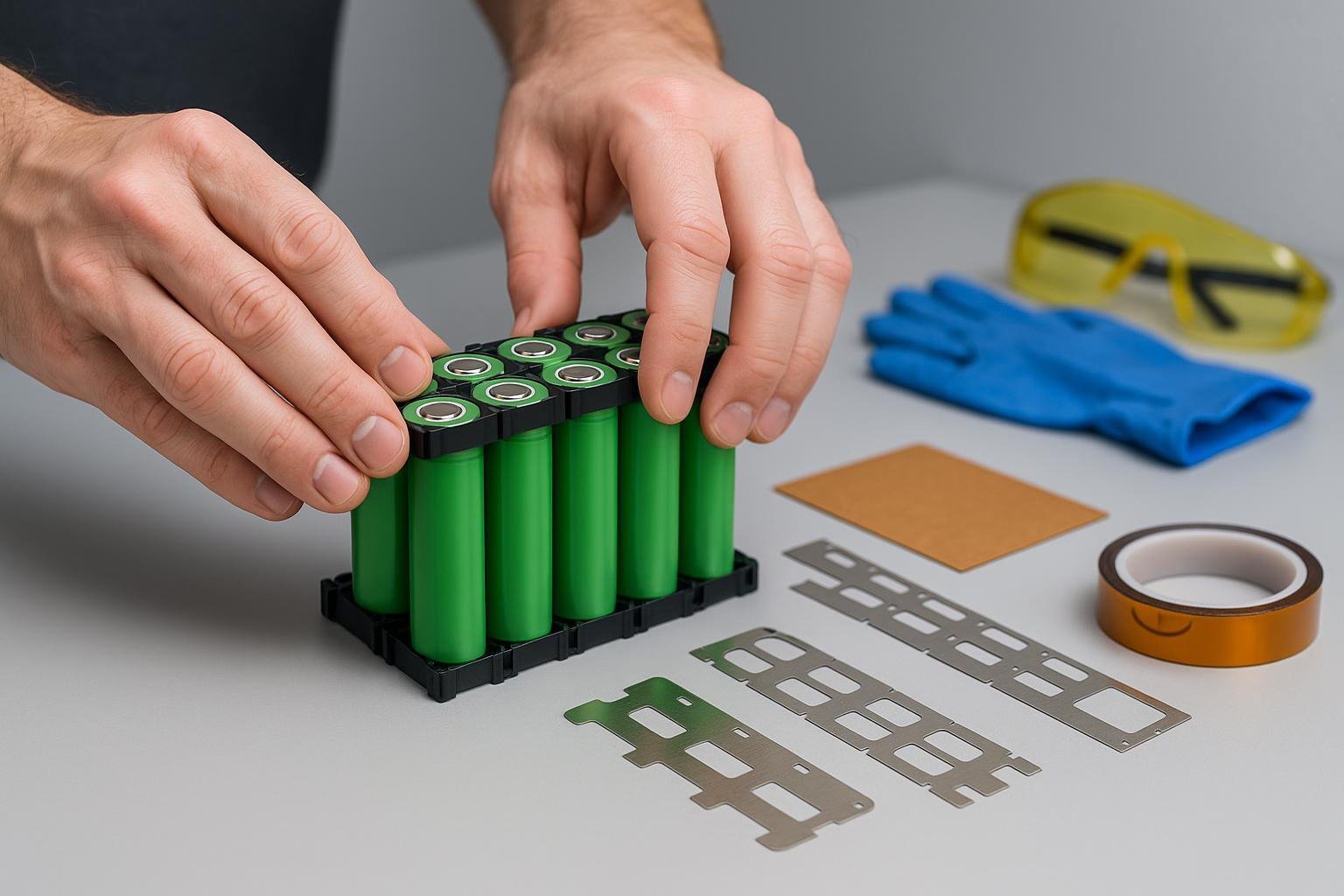
| Insulated gloves & safety goggles | Mandatory for all assembly | |
| Spot welder (preferred) or battery-safe soldering iron | Spot welder highly recommended (Guide) | |
| Nickel strips (pure, battery-grade) | For cell interconnects | |
| Multimeter | For voltage/continuity checks | |
| Cell holders/spacers | Prevent stress, maintain alignment | |
| Fish paper rings & Kapton tape | Insulate positive terminals/all contacts | |
| Heat shrink tubing | For final pack insulation | |
| Fire extinguisher (ABC/CO2) / no metal clutter | Must be immediately accessible | |
| Ventilated, non-flammable workspace | No flammable surfaces! | |
| Pre-tested, matched 18650 cells (voltage/capacity/IR) | Test every cell—log results (Cell Guide) |
(For a printable version and wiring templates, see Resource Section.)
🔋 Step 1. Planning Your Pack: Configuration & Cell Selection
Define your goal:
- Target Voltage:
- Series cells = voltage (e.g., 4 cells in series × 3.7V = 14.8V)
- Target Capacity:
- Parallel cells = amp-hour capacity (e.g., 3 cells parallel × 2.5Ah = 7.5Ah)
- Utiliser un Pack Planner or simple table to visualize configuration.
- Target Voltage:
Test & Match Each Cell:
- Measure voltage: All should be within 0.05V of each other.
- Check internal resistance: Remove high-resistance cells.
- Log results: Label/stage cells to avoid mix-ups.
Pre-Visual Layout:
- Dry-fit all cells into holders/spacers matching your diagram (see layout templates).
- TIP: Alternate orientation (flip every other row) for easier wiring and balance leads.
🏗️ Step 2. Arranging & Aligning Cells Safely
Arrange cells in holders/spacers:
- Use plastic cell holders or 3D-printed frames for neat, stable alignment and airflow. This dramatically reduces shorts and cell movement issues (visual example).
Install fish paper rings:
- Place an insulating ring (fish paper/Kapton) over each cell’s positive end—never skip (this prevents accidental shorting by nickel strips).
Dry-fit full configuration:
- All positives/non-positives must face as per your wiring diagram! Double-check orientation before any welding/soldering.
Common Mistake Callout:
- Misaligned cells cause stress and shorts—always re-check layout!
🔗 Step 3. Electrical Connections: Spot Welding or Soldering
Spot Welding (Preferred Method)
- Set up spot welder: Adjust settings for clean, solid welds on nickel strips—practice on dummy cells first.
- Weld parallel groups:
- Lay nickel strips across cells in each parallel row. Tap two or more welder spots per terminal.
- Weld series connections:
- Bridge parallel groups with nickel, keeping wiring as short and straight as possible.
- Check connections: Each weld should:
- Be shiny and solid;
- Withstand a gentle tug (pull test);
- Have no burned spots or weak bridges.
Soldering (Only if Absolutely Necessary & With Care!)
- Use a powerful iron (60W+), battery-safe solder, work quickly (<2s per joint). Direct heat damages cells!
- NEVER solder directly to positive terminal top.
- Allow cells to cool frequently.
Troubleshooting Tip:
- Cold welds? Re-weld after cleaning surface and adjusting welder settings (technique source).
- Loose wires? Respot or carefully resolder, ensuring nickel is flat and tight.
🧰 Step 4. BMS, Insulation & Final Securing
Attach BMS (Battery Management System)
- Solder balance leads in sequence (B-, B1, B2, … B+, as per diagram)—follow manufacturer manual exactly! (Guide BMS)
- Double-check polarity before connecting main leads—mistakes can destroy pack/BMS.
Insulate everything:
- Wrap exposed metal and connections with Kapton tape or fish paper.
- Slide on tight heat-shrink tubing for whole pack, shrink with hot air.
Final mechanical securing:
- Hot glue between cell groups or to holder as needed to prevent movement.
- Place completed block in a non-conductive, robust outer case if desired.
✅ Step 5. Quality Checks & Final Inspection (QA)
Essential Pass/Fail Checklist
- [ ] No exposed nickel/wires visible
- [ ] All cells firmly locked, no movement
- [ ] Measured pack voltage matches design
- [ ] All parallel groups within 0.05V
- [ ] All insulation intact, with no exposed terminals
- [ ] BMS connections verified by continuity test
- [ ] No abnormal heat, arcing, or sparks
Functional test: Briefly apply a moderate load with a tester (e.g., light bulb, resistor bank) and measure voltage drop/temperature.
🩺 Troubleshooting Table: Fast Fixes for Common Problems
| Symptôme | Likely Cause | Solution |
|---|---|---|
| Cells not aligned | Wrong spacers/layout | Realign, use holders or re-stage layout |
| Cold/weak welds | Low power/unprepared surface | Clean tabs, increase welder output, retry |
| Loose wires/parallels | Weak solder or weld | Re-solder/re-weld, reinforce/wrap |
| BMS doesn’t turn on | Wrong balance lead order | Review diagram, resolder in correct sequence |
| Exposed tabs after shrink | Incomplete wrap | Add tape/fish paper, reheat-shrink |
| Excess temperature | Bad contact, solder overheat | Check all joints, replace damaged cells |
(For a printable troubleshooting flowchart, see recommended template.)
📥 Resources & Downloadables
- Cell and Pack Layout Planner (online visual tool)
- Wiring Diagrams: Typical Configurations
- Printable Preparation & QA Checklist
- Spot Welding Tips & Repairs
- Regulatory & Safety Codes: UN 38.3, IEC 62133
❓ Frequently Asked Questions (FAQ)
Q1: Is spot welding always better than soldering for 18650 packs?
A: Yes, spot welding produces lower resistance, safer connections, and less thermal damage (in-depth explanation).
Q2: My pack doesn’t charge—what should I check?
Verify all BMS leads in the right order, ensure no wires are loose or reversed, and check for matching cell voltages.
Q3: Can I safely repair a cold weld after pack assembly?
Yes, carefully re-spot or re-solder after isolating the affected group—and always re-insulate. If damage is suspected, replace the cell.
Q4: How long does a DIY 18650 pack last?
With quality cells, proper welding, and balanced charge/discharge, expect 300–800 cycles—lifespan varies by use and maintenance.
🚨 Final Safety Reminders
- Never build packs with mismatched, old, or unknown cells.
- Toujours utiliser dedicated spot-welders for main cell interconnects.
- Double-insulate every exposed terminal and tab.
- Test pack outside, away from people/flames, during first charge/discharge.
📚 Further Learning & References
Takeaway: With patience, respect for safety, and this stepwise workflow, you can build a durable, safe 18650 battery pack. Print the checklists, double-check every stage, and never cut corners on insulation or testing. Happy building—and stay safe!