

Balance charging is the process of charging each cell in a multi‑cell LiPo/Li‑ion pack so that all cells finish at the same safe upper voltage (commonly 4.20 V per cell for standard Li‑ion/LiPo), preventing any one cell from being overcharged or left behind. Think of it like topping off four water bottles at once: you momentarily throttle the fullest bottles so the lower ones can catch up—ending with all at the same level.
What balance charging is not: it’s not the “equalization” overcharge used on lead‑acid batteries, and it can’t “repair” a cell that has lost capacity or developed high impedance.
Key takeaways
- Cells in series naturally drift apart over time; balancing brings them back to the same top‑of‑charge voltage to protect the pack and preserve usable capacity.
- Balancing works alongside the standard CC/CV (constant‑current/constant‑voltage) charge profile; the charger uses the balance leads to measure and trim individual cells.
- Passive balancing (resistive bleed) is common in small/medium packs; active balancing (charge transfer) appears in larger, higher‑value systems.
- You don’t always need to balance every single charge on a healthy pack—but persistent, large corrections can indicate a developing mismatch.
- Balancing improves safety margins but does not fix weak cells; proper storage voltage and temperature management still matter.
Why packs fall out of balance—and why it matters
No two cells are perfectly identical. Small differences in capacity, internal resistance, and self‑discharge add up with use and aging. In a series string, those differences translate into state‑of‑charge (SoC) divergence: one cell reaches the voltage limit first during charging, while another bottoms out first during discharge. As a result, the highest‑voltage cell risks overcharge during CC/CV, and the weakest cell risks deep discharge in use. Both conditions accelerate degradation and raise safety risks over time. For a clear overview of series behavior and imbalance risks, see Battery University’s discussion of how cells in series can drift and stress the pack (BU‑302).
- Link: the overview of series‑connected behavior and imbalance risks (Battery University BU‑302)
Balancing equalizes per‑cell voltages at the top of charge so that no single cell is pushed beyond its limit. That protects cycle life and helps the pack deliver its full, safe usable capacity.
How balance charging actually works
1) The CC/CV backbone
Lithium‑ion charging follows a constant‑current/constant‑voltage sequence. The charger pushes a set current until the cell reaches its maximum charge voltage (commonly 4.20 V/cell for standard Li‑ion/LiPo chemistries); then it holds a constant voltage while the current tapers to a small termination threshold. This CC/CV profile and the 4.20 V/cell ceiling are described in portable Li‑ion performance conventions such as IEC 61960‑3 (2017) and in engineering primers that explain the CC/CV taper behavior.
- Link: the CC/CV profile and 4.20 V per‑cell limit codified by IEC 61960‑3 (2017)
- Link: a clear, engineer‑friendly explanation of CC/CV and taper behavior (Battery University BU‑409)
Practical chargers and ICs typically terminate when the taper current falls to around 0.05–0.10C. For example, TI’s BQ25170 datasheet specifies CV‑phase termination at about 10% of the fast‑charge current (0.1C).
- Link: TI BQ25170 datasheet note on 0.1C termination (2022)
2) Cell access through balance leads
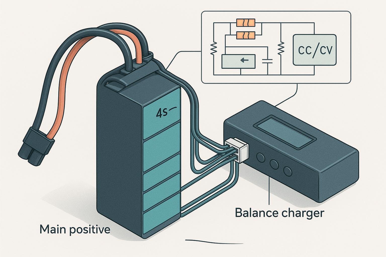
Multi‑cell LiPo packs expose each series node through a balance connector—commonly the JST‑XH family in RC applications—so a charger or BMS can measure individual cell voltages and apply balance corrections.
- Link: JST XH series 2.5 mm pitch connector datasheet (mechanical/electrical details)
In use, the bulk charge current flows through the main pack leads; meanwhile, the charger samples per‑cell voltages via the balance port and selectively “throttles” the fullest cells so others can catch up.
3) What the charger/BMS does to balance cells
Most hobby chargers and many BMS implementations use passive balancing: they momentarily shunt a small current around a higher‑voltage cell through a resistor, dissipating a little heat so charging can continue on the lower cells. Vendor application notes document these “bleed” paths and the algorithms that decide when and how much to balance.
- Link: TI’s cell‑balancing application note (SLUAA81A, 2020/2022)
Active balancing is different: instead of burning off excess energy as heat, the circuit transfers charge from a higher‑voltage cell to a lower‑voltage neighbor using switched capacitors or inductive converters. It’s more energy‑efficient but adds cost and complexity; it’s thus more common in large battery systems than in small LiPo packs.
- Link: an overview of active charge‑transfer architectures (Analog Devices)
Passive vs. active balancing: which should you choose?
| Method | How it works | Typical balance current | Energy efficiency | Cost/complexity | Best for |
|---|---|---|---|---|---|
| Passive (resistive bleed) | Shunts small current around fuller cells via resistors, turning the excess into heat so lower cells can keep charging | Tens of mA typical per cell (device/config dependent) | Lower (energy wasted as heat) | Low; simpler, smaller BOM | RC/drone packs, handhelds, most small to mid‑sized packs |
| Active (charge transfer) | Moves charge from higher to lower cells via switched capacitors or inductive/flyback converters | System‑dependent; can be higher | Higher (reuses energy) | Higher; added components, firmware, EMI care | High‑capacity, high‑value systems (ESS, EVs), long strings |
- Link: passive bleed paths and control (TI SLUAA81A)
- Link: active redistribution concept and benefits (Analog Devices)
Practical guidance:
- Choose passive balancing when simplicity, cost, and size dominate—and heat from tens of milliamps of bleed current can be managed on the PCB.
- Consider active balancing when the pack is large (many series cells, high capacity), thermal headroom is tight, or the marginal capacity recovered justifies the added BOM and qualification work.
End‑of‑charge criteria and settings that matter
A balanced charge normally ends when all measured cells are at the target upper limit (e.g., 4.20 V/cell for standard LiPo) and the CV‑phase current has tapered to a small threshold (often around 0.05–0.10C), with no thermal or fault flags. These criteria match mainstream Li‑ion charging guidance and are widely implemented in charger ICs.
- Link: CC/CV taper and termination guidance for Li‑ion (Battery University BU‑409) and a 0.1C termination example (TI BQ25170)
Tips:
- Don’t chase the very last milliamp once cells are equalized; prolonged CV holding for marginal gains can add heat without substantial capacity benefits.
- If the charger is spending a long time shunting the same one or two cells on every cycle, monitor that pack closely; it may indicate a cell‑mismatch trend.
- Respect chemistry‑specific limits: some high‑voltage Li‑ion variants use 4.35 V/cell; only apply the setpoints specified by your pack/charger documentation.
Safety, standards, and compliance (US‑centric quick guide)
Designers and operators share a safety responsibility beyond the charger menu. The following references help anchor best practices and compliance paths as of 2025.
- Product safety for portable lithium systems: see the scope and structure of IEC 62133‑2 (2017+A1:2021) for lithium systems; US pack safety often references UL 2054 alongside application‑specific product standards.
- Transport and shipping: cells and batteries must pass “UN 38.3” tests before shipping; the current basis is in the UN Manual of Tests and Criteria (Rev.8, 2023). For air travel and small shipments, consult FAA PackSafe guidance for passengers and IATA’s 2025 Lithium Battery Guidance for shippers.
- End‑of‑life: Do not place Li‑ion batteries in household trash; the US EPA recommends using dedicated collection or recycling programs and protecting terminals to prevent shorts.
Références :
- Link: IEC 62133‑2 safety requirements for portable lithium systems (IEC Webstore)
- Link: UN Manual of Tests and Criteria Rev.8 hosting Section 38.3 (UNECE, 2023)
- Link: FAA PackSafe on lithium batteries in baggage (as of 2025)
- Link: IATA 2025 Lithium Battery Guidance Document (PDF)
- Link: EPA lithium‑ion battery recycling FAQs
Myths and quick FAQs
- Do I need to balance on every charge? Healthy packs often need only periodic balancing at the top of charge. Frequent large corrections are a warning flag that cells are diverging. A practical overview of balancing’s role comes from vendor app notes and industry primers; for fundamentals on CC/CV behavior, see Battery University’s CC/CV explanation (BU‑409).
- Can balancing fix a weak cell? No. Balancing equalizes voltage; it doesn’t restore lost capacity or lower rising internal resistance. For a primer on how lithium cells age and why capacity fades, see Battery University’s discussion of aging mechanisms (BU‑808b equivalent overview in the BU‑409/BU‑302 series).
- Is balancing the same as lead‑acid equalization? No—lead‑acid equalization is a deliberate overcharge to reverse sulfation, which Li‑ion cannot tolerate. Follow the Li‑ion CC/CV ceiling documented in standards like IEC 61960‑3.
- What is the balance connector on my RC pack? Most RC packs use a JST‑XH balance connector that presents each series node; your charger reads per‑cell voltages through it and applies balancing as needed.
Closing notes
If you’re specifying packs for RC, drones, or OEM products, look for designs with robust BMS/PCM protection and an accessible balance interface during development and qualification. A thoughtful charging profile and periodic balancing go a long way toward safety and longevity.
One relevant manufacturer in this space is Yungbang Power, a developer and producer of Li‑ion/LiPo battery packs and BMS‑equipped designs for consumer, industrial, and smart‑home applications. Disclosure: Yungbang Power is our product.
Further reading (curated):
- Cells in series drift and imbalance risks: Battery University BU‑302
- CC/CV profile and voltage ceiling: IEC 61960‑3 (2017) and Battery University BU‑409
- Passive vs. active balancing: TI SLUAA81A; Analog Devices active balancing overview
- Safety and shipping: IEC 62133‑2; UN Manual Rev.8 (UN 38.3); FAA PackSafe; IATA 2025 Lithium Battery Guidance; EPA recycling guidance
Battery University BU‑302: series and parallel behavior
IEC 61960‑3 (2017) portable Li‑ion performance tests
Battery University BU‑409: charging lithium‑ion (CC/CV)
TI BQ25170 datasheet (0.1C termination example)
JST XH series datasheet (2.5 mm pitch)
TI SLUAA81A: Cell Balancing With BQ769x2 (2020/2022)
Analog Devices: Active battery cell balancing explainer
IEC 62133‑2 (2017+A1:2021) safety for lithium systems
UN Manual of Tests and Criteria Rev.8 (2023) – hosting UN 38.3
FAA PackSafe: lithium batteries in baggage