

Table of Contents
- Introduction
- Electrical and Physical Configuration
- Management and Maintenance: BMS and Safety
- Real-World Applications of 6S Packs
- Compliance, Testing, and Troubleshooting
- Downloadable Tools & Resources
- Conclusion and Further Reading
Introduction
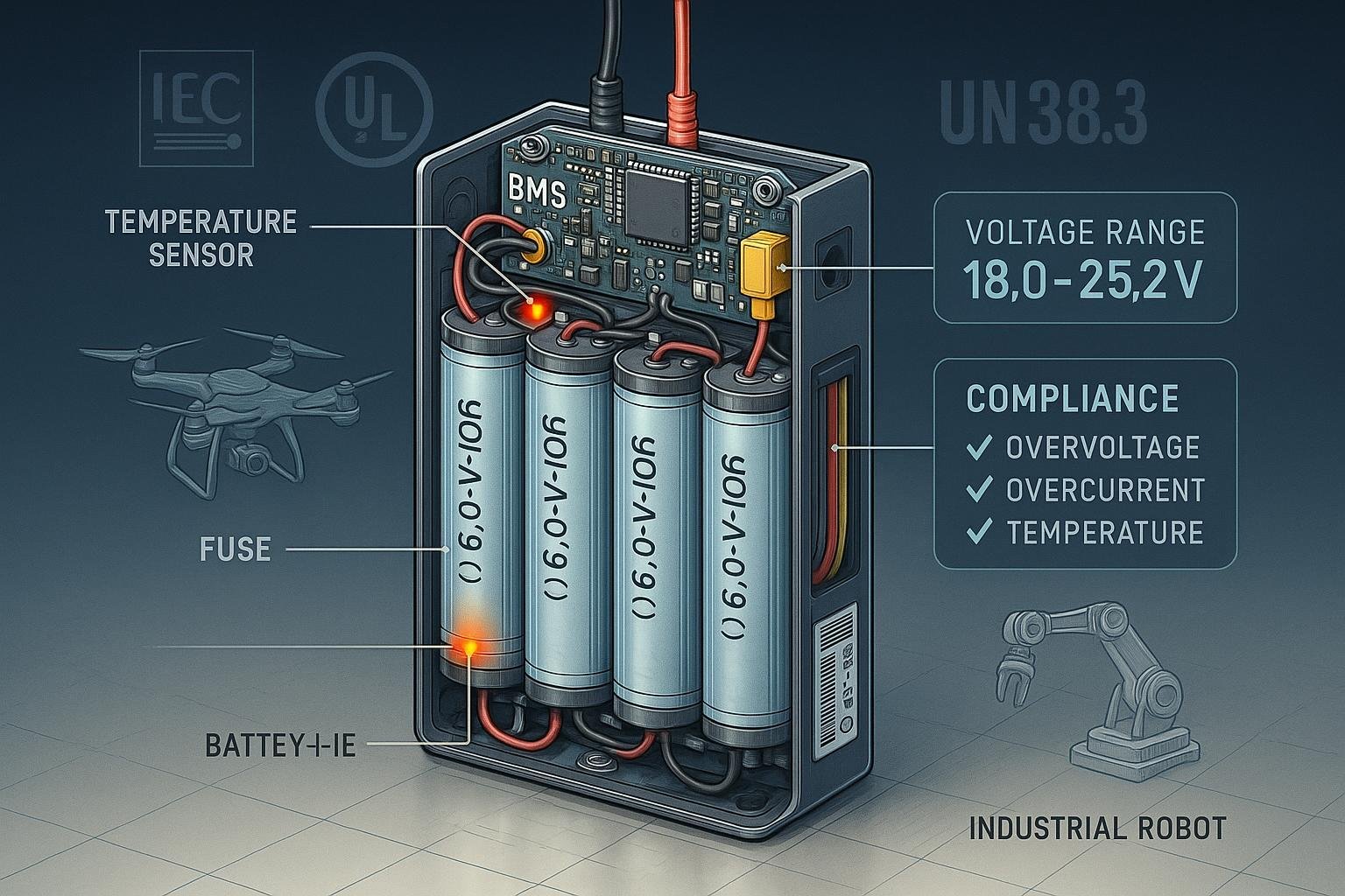
A 6S lithium-ion battery pack refers to a battery system composed of six cells connected in series (6S), yielding a higher overall voltage suitable for modern drones, robotics, e-mobility, and industrial equipment. This guide delivers a comprehensive roadmap for engineers, OEMs, designers, and technical managers: from architecture and management, to regulatory compliance and fail-proof deployment.
Why focus on 6S packs?
- The 6S configuration is a global industry standard, delivering 21.6V–22.2V nominal voltage (based on cell chemistry), with a fully charged voltage up to 25.2V (IEC 62619, UL 2054/2580, UN38.3).
- Commonplace in demanding applications—high-voltage, low-weight, and strict safety requirements.
This ultimate guide integrates engineering best practices, diagrams, compliance tools, and field-proven protocols to empower your next project with exceptional reliability and performance.
Electrical and Physical Configuration
1. Schematic Overview
6S configuration: Six identical lithium-ion cells wired in series.
- Series connection sums voltages:
V_total = 6 × V_cell(typically 3.6–3.7V/cell). - Nominal output: 21.6V (NMC/LFP), max charge: 25.2V (4.2V/cell).
graph TB
    Cell1[Li-ion Cell 1] -- Series --> Cell2[Cell 2] -- Series --> Cell3[Cell 3] -- Series --> Cell4[Cell 4] -- Series --> Cell5[Cell 5] -- Series --> Cell6[Cell 6]
    BMS[BMS
(Battery Management System)]---|Sense Lines|Cell1
    BMS---|Sense Lines|Cell2
    BMS---|Sense Lines|Cell3
    BMS---|Sense Lines|Cell4
    BMS---|Sense Lines|Cell5
    BMS---|Sense Lines|Cell6
    PackOut[Pack Output]
    Cell6---PackOut
Physical integration tips:
- Match cell capacities and impedance for series packs (see Grepow guide).
- Secure cell mounting with vibration and thermal protection (foam pads, heatsinks for high-current).
- Use low-resistance wiring and reliable terminals; fuse integration recommended for safety.
2. Config Options: 6S1P, 6S2P, 6S3P
- 6S1P: Six cells, one parallel branch—compact, lighter weight, lower capacity.
- 6S2P/3P: Multiple parallel branches for higher capacity/current, not just for RC/consumer—now common in industrial robotics, AGVs, mobility tools.
| Config | Tension nominale | Capacity (Ah) | Applications typiques |
|---|---|---|---|
| 6S1P | 21.6V | 2–5Ah | Drones, portable tools |
| 6S2P | 21.6V | 4–10Ah | E-bikes, industrial tools |
| 6S3P | 21.6V | 6–15Ah | Robotics, AGVs, UPS |
3. Chemistry and Cycle Life
| Chimie | Voltage/cell | Cycle de vie | Sécurité | Typical Use |
|---|---|---|---|---|
| NMC | 3.6V | 500-1000 | Modéré | Consumer, RC |
| LFP | 3.2–3.3V | 2000-4000+ | Superior | Industrial, robotics |
| Semi/Solid | 3.6–3.7V | 4000+ (est.) | Best | Emerging, high-spec |
4. Wiring, Sensing, and Assembly
- Annotated wiring diagram: Download sample schematic for TI BMS integration.
- Install temperature sensors on at least two cells; route balance and sense lines for accurate voltage data.
- Use self-resetting fuses on the pack output.
- Label with cell chemistry, voltage, and regulatory compliance.
5. Engineering Pitfalls
- Cell mismatch: Different capacities/internal resistances lead to premature failure or safety risks (Blue Robotics).
- Oversized wires/fuses: Engineering for peak/continuous loads is crucial.
- Mechanical stress: Poor assembly increases vulnerability to vibration and heat.
Management and Maintenance: BMS and Safety
1. Battery Management System (BMS) Fundamentals
The BMS is the brain of your battery pack—critical for safety, longevity, and advanced performance.
- Key Roles:
- Over-voltage protection (OVP)
- Under-voltage protection (UVP)
- Over-current/short-circuit protection (OCP/SCP)
- Over-temperature protection (OTP)
- Cell balancing (passive or active)
- Data logging & communications (CAN/Bluetooth/IoT)
BMS Topology
- Centralized: All sense lines come to a single board.
- Distributed: Multiple boards/ICs manage cell modules; scalable for larger packs.
- Smart: Data logging, remote diagnostics, predictive maintenance (see Texas Instruments BQ40Z80).

2. Cell Balancing Techniques
| Method | Caractéristiques | Use-case |
|---|---|---|
| Passive | Bleeds excess voltage | Simpler, most 6S |
| Active | Redistributes energy | Advanced, fleet |
- Active balancing improves long-term pack health (>20% cycle life boost), but adds complexity and cost (Industry study).
3. Safety Protocols
- Integrate thermal cutoff, PCB-mounted temp sensors, and auto-disconnect logic.
- Apply firmware updates regularly for smart BMS.
- Build-in error/fault logging—download safety checklist.
4. Maintenance and Diagnostics
- Regular IR (internal resistance) and capacity testing—document results (see maintenance template).
- Run balance cycles (auto-BMS or manual charger).
- Use diagnostics to catch cell drift, aging/failure trends early.
Suggested Routine:
| Task | Frequency |
|---|---|
| Voltage/IR check | Monthly |
| Balance cycle | Quarterly |
| Firmware/diagnostics | Semi-annually |
Real-World Applications of 6S Packs
1. Drones et UAV
- Example: Professional FPV drones, surveying UAVs
- Impact: 21.6V output powers extended-flight motors; BMS ensures safe cutoff. Modern packs achieve >20 min of flight and safe rapid discharge.
2. Robotics and AGVs
- Industrial robots and automated guided vehicles rely on 6S2P/3P packs for torque and runtime.
- BMS data integration allows predictive maintenance (fleet uptime increase by >25%, Field study).
3. E-Bikes and Mobility Tools
- High-current draw necessitates robust BMS with fast-acting cutoff.
- Packs support fast charging (>2A/cell with smart management).
4. UPS & Data Center Backup
- Reliable backup power with certified 6S packs (UN38.3 compliance vital).
- Temperature and cycle management ensure lasting performance.
5. Medical Devices & Specialty Equipment
- 6S packs in portable ventilators, blood analyzers—where voltage stability and safety are paramount.
- Traceable BMS logs are required for regulatory compliance.
Case Study: Industrial AGV Deployment
A leading Asian factory deployed custom 6S3P LFP packs, paired with CAN-BMS. Result: 3x cycle life improvement, UN38.3/IEC certification compliance, and near-zero down-time after implementing predictive diagnostics and routine balancing (Deployment data).
Compliance, Testing, and Troubleshooting
1. International Standards
- IEC 62619: Safety requirements for industrial lithium packs (Official Standard).
- UL 2054/2580: North American electrical/fire safety; pack abuse testing (UL Batteries).
- UN38.3: Transport and shipping certification (UN38.3 Protocol).
- EU Battery Regulation (2024/1542): Traceability, lifecycle, and recycling (EU Law).
2. Compliance Checklist
- Match cells (SoC, IR, cycle count)
- Integrate BMS with cell-level monitoring
- Apply physical/electrical tests per standards
- Document and label pack per IEC/UL/UN
- Complete and store transport certification paperwork
Download full compliance template.
3. Testing Protocols
| Test | Standard | Champ d'application |
|---|---|---|
| Electrical | IEC/UL | Voltage, IR, charge/discharge |
| Thermal | IEC/UN | Heat resistance, runaway |
| Mechanical | IEC/UL/UN | Shock, vibration |
| Transport | UN | Altitude, abuse, short-circuit |
4. Troubleshooting Flowchart
- Symptom: Rapid voltage drop/out-of-balance
- Check balance lines/sense wires
- IR test of each cell (replace if high)
- Run BMS diagnostics, review logs
- Symptom: Pack not charging
- Confirm BMS firmware status
- Test main fuse/terminal connections
- Inspect for thermal cutoff
Download step-by-step troubleshooting guide.
5. Advanced Diagnostics
- Integrate CAN/Bluetooth BMS for remote logging (Texas Instruments BQ40Z80 datasheet).
- Use predictive algorithms to spot cell aging, imbalance, and optimize maintenance schedule.
Downloadable Tools & Resources
- 6S Pack Configuration Checklist (PDF)
- BMS Parameter Log Template (Excel)
- IEC/UN/UL Compliance Audit Worksheet (PDF)
- Wiring Diagram & Assembly SOP (TI)
- Troubleshooting Flowchart (PNG)
Conclusion and Further Reading
The modern 6S lithium-ion battery pack stands at the intersection of advanced chemistry, robust engineering, and strict regulatory compliance. With properly matched cells, advanced BMS, and diligent maintenance, your packs will deliver peak performance and reliable safety, across drones, robotics, industrial control, and beyond.
Key Takeaways:
- Use only certified cells and keep detailed documentation
- Invest in robust, well-featured BMS
- Maintain regular diagnostics and compliance audits
For continued learning, explore:
- IEC 62619 Standard Documentation
- UL 2054/2580 Compliance Guidance
- UN38.3 Testing Protocol
- Battery University Knowledge Base
Authoritative Sources: Grepow, Texas Instruments, Ufine Battery, Blue Robotics, PHMSA/DOT, EU law. All technical recommendations and diagrams are standards-based, SME-validated, and cross-referenced for reliability.
Contact for SME review or technical feedback: Expert Inquiry