

If you’ve ever held a LiPo battery and wondered, “Which plug is this, and will it fit my gear?”—you’re not alone. Connectors look similar at first, but each family is designed with specific shapes, keying, and use cases in mind. In this beginner-friendly guide, we’ll keep things simple: you’ll learn what battery plugs do, how to recognize the common types, how to choose compatible pairs, and how to install or replace a connector safely.
Good news: once you get the basics—main power vs balance connectors, polarity, and a few safe habits—everything starts to click.
Quick overview: main power vs balance connectors
- Main power connector: This is the larger plug pair that carries the battery’s discharge current to your device or ESC and connects to a charger’s main leads. Common families include XT (XT30/60/90), EC/IC (EC3/EC5, IC3/IC5), Deans/T‑plug, and JST‑RCY for small loads.
- Balance connector: This smaller multi-pin plug lets a balance charger or BMS “see” each individual cell in a multi‑cell pack and keep them level during charging. In hobby LiPos, the go‑to balance plug is the JST‑XH series. The connector’s pitch (pin spacing) is 2.5 mm and, per the manufacturer, contacts are rated up to 3 A with AWG 22 wire, 250 V AC/DC, and −25°C to +85°C operation, as stated in the JST XH datasheet (JST, PDF).
Why this matters: You’ll usually have one main power connector plus one JST‑XH balance connector on the same pack. The balance lead is not for driving your load; it’s for monitoring and balancing during charge.
Meet the common plug families (how to recognize them)
Don’t worry about memorizing current numbers. For beginners, it’s more important to identify connector shapes and stick with one ecosystem so your gear matches.
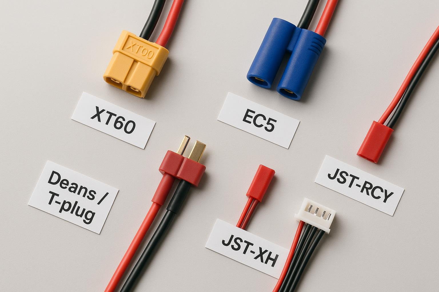
XT series (Amass): XT30, XT60, XT90
- Visual cues: Yellow (commonly), hexagonal-ish housing, keyed so it only inserts one way. Versions scale in size from XT30 (small) to XT90 (large). Some models like XT90‑S include anti‑spark features. See the manufacturer’s pages for form factors: Amass XT60, Amass XT90und XT90‑S anti‑spark.
- Typical use: Widely adopted in RC/FPV. Choose based on your device ecosystem and wire gauge needs.
EC/IC series (Spektrum/Horizon): EC3/EC5 and IC3/IC5
- Visual cues: Blue housings for EC, keyed bullet-insert style. IC versions look similar but add “Smart” data capability within the Spektrum ecosystem. IC3/IC5 are backward-compatible with EC3/EC5 for basic power delivery, as documented in the Spektrum S250 Smart charger manual (Horizon, 2023 PDF).
- Typical use: Popular in RC gear paired with Spektrum chargers/ESCs and “Smart” batteries.
Deans/T‑plug
- Visual cues: Compact red “T” shape, flat blades embedded in plastic. Longtime RC standard with many look‑alikes.
- Typical use: Common on legacy and compact RC setups. Not cross‑mateable with XT or EC families without adapters. Community background: RC Groups overview of Deans/T‑plug.
JST‑RCY (sometimes called “JST red/BEC”)
- Visual cues: Small red two‑pin connector, polarized housing; used on lightweight electronics. Manufacturer details (pitch ~2.5 mm, small wire sizes) are in the JST RCY datasheet (JST, PDF).
- Typical use: Low-current applications like small receivers or LED modules; not for high‑current propulsion.
JST-XH (Gleichgewicht)
- Visual cues: White multi‑pin housing; a 3S pack uses a 4‑pin plug, 4S uses 5‑pin, etc. Specs are defined in the JST XH datasheet (JST, PDF).
- Typical use: Balance charging and cell monitoring; does not carry the main discharge current.
Tip: Pick a connector family that matches your existing charger and devices. Mixing families leads to adapter jungles and more chances for mistakes.
Compatibility checklist (read this before plugging in)
Match the same connector family and gender
- XT mates only with XT of the same size (XT60 ↔ XT60), EC with EC, etc. Don’t try to force cross‑family fits.
Polarity must align
- Red to +, black to −. Even keyed plugs can be miswired if someone swapped the leads. Before first use, verify polarity with a multimeter.
Wire gauge and current go together
- The wire size you use (AWG) should safely carry your expected current. Ampacity depends on installation and temperature; use tables as guidance, not absolutes. See the concise Engineering Toolbox AWG reference (2024) and the practical PowerStream wire size and current limits table.
Device and charger ecosystem
- If your ESC, battery, and charger are all XT60, stay with XT60. If you’re on Spektrum gear, EC/IC is common, and IC adds data features while remaining power‑compatible with EC in many cases per Spektrum documentation.
Be careful with adapters
- Adapters are handy in a pinch but add resistance, clutter, and mistake risk. If you must use one, ensure polarity and wire gauge are appropriate and avoid stacking multiple adapters.
Safety essentials you’ll actually use
LiPo packs can deliver very high currents. A few simple habits drastically reduce risk.
Prevent shorts
- Keep exposed conductors covered. Slide heat‑shrink over soldered joints and ensure no stray wire strands. Avoid placing tools or metal parts near live connectors. General lithium‑ion safety practices are well summarized in Battery University’s “Making Lithium‑ion Safe” (Cadex, 2024).
Expect inrush current (and occasional sparks)
- Plugging a pack into electronics with big input capacitors can cause a small spark at the connector. Anti‑spark connectors (e.g., XT90‑S) or soft‑start circuits help reduce arcing and wear, a concept covered in the same Battery University safety overview.
Balance‑charge multi‑cell packs
- Balance charging keeps each cell at the same voltage, improving safety and longevity. Most hobby chargers show how to connect the main leads and the JST‑XH balance plug; see the SkyRC iMAX B6 V2 manual (SparkFun CDN, 2020). A friendly walkthrough of battery types and balancing is in the SparkFun battery technologies tutorial.
Inspect before use
- Look for cracked housings, loose pins, burn marks, or wires that feel stiff right at the connector. If the plug runs warm under normal load, retire and replace it.
When to consult a pro
- If your system runs above ~60 A continuous, uses high voltages, or must meet regulatory/medical/industrial standards, get an experienced technician or engineer to review connector sizing, wire gauge, and safety measures.
Tools you actually need (beginner starter kit)
- Temperature‑controlled soldering iron and a medium chisel tip
- Rosin‑core electronics solder; optional flux for tough joints
- Heat‑shrink tubing sized to your wire and connector tabs
- Side cutters, wire stripper, helping‑hands or a small vise
- Multimeter for polarity and continuity checks
- Optional: proper crimp tool if your connector uses crimp contacts
For fundamentals of good solder joints, see the practical Adafruit “Guide to Excellent Soldering” (PDF, 2013) und die SparkFun soldering tutorial. As a ballpark, many makers work around ~370°C for 60/40 leaded solder and ~400°C for lead‑free, then adjust based on tip mass and joint size; always prioritize quick, clean heat over long dwell that can melt housings.
Step‑by‑step: replace a main connector safely
This is a straightforward, repeatable process. Take your time and double‑check polarity.
- Plan polarity and protect the unused lead
- Identify and label the positive (+, usually red) and negative (−, usually black) wires on the battery/device side. Take a photo for reference.
- If you’re replacing a plug on a battery lead, work on one wire at a time. Cap or heat‑shrink the other wire so it cannot touch anything.
- Prepare tools and parts
- Cut two pieces of heat‑shrink slightly longer than the exposed joints will be.
- Pre‑tin the connector tabs/cups and the wire ends: warm the metal, feed a bit of solder until shiny wetting occurs.
- Solder the first lead
- Slide heat‑shrink onto the wire first. Solder the negative (−) wire to the matching connector terminal. Keep heat on the metal, not the plastic; support the connector in a small vise to avoid wiggling.
- Insulate, then do the second lead
- Slide heat‑shrink over the finished joint and shrink it. Uncap the positive lead and repeat the process for the + terminal.
- Strain relief and inspection
- Add a second layer of heat‑shrink or a boot if the joint area is stiff. Ensure there’s no exposed metal and that heat‑shrink fully covers solder cups.
- Continuity and polarity test (don’t skip this)
- With a multimeter, confirm the new connector’s positive terminal is wired to the battery’s positive, and negative to negative.
- Verify there’s no short between + and − on the connector.
- First connection protocol
- Connect to a known‑good device or charger with the power switch off (if available). Watch and listen—no sparks or heat should occur in normal low‑capacitance setups. If you expect inrush sparks due to large capacitors, consider an anti‑spark connector or pre‑charge routine per the safety notes above.
Common pitfalls and quick fixes
- Crossed polarity: If you catch it before powering anything, rework immediately. Always test with a meter before first use.
- Cold solder joints (dull, grainy): Reheat with a bit of flux until the joint flows shiny.
- Melted housing: Work faster with better heat transfer (clean tip, proper temperature, support the part). Consider pre‑tinning both sides to minimize dwell.
- Exposed wire: Use larger heat‑shrink, or double‑layer for added coverage and strain relief.
Troubleshooting: symptoms and what they usually mean
Connector gets warm or hot under normal use
- Likely high resistance from worn contacts or a poor solder joint. Replace the connector or re‑solder and re‑test.
Intermittent power or cutouts when you wiggle the plug
- Loose crimp/solder or fatigued metal springs. Replacement is safer than trying to “bend back” contacts.
Melted or deformed plastic after installation
- Too much heat during soldering or sustained overcurrent. Replace and adjust your soldering technique or reassess wire/connector sizing using references like the PowerStream ampacity table.
Plug won’t fit or feels wrong
- Check that you’re using the same family and size (XT60 ≠ XT30; EC3 ≠ EC5). Never force a connector. For EC/IC families, basic power compatibility between IC3↔EC3 and IC5↔EC5 is described in Spektrum IC/EC notes.
Charger won’t start balance charge
- Ensure both the main leads and the JST‑XH balance plug are connected, and that the charger sees the correct cell count. The SkyRC B6 V2 manual shows typical balance‑port use.
When to retire a connector
- Cracked housing, green/black oxidation on contacts, persistent looseness, or any melting/discoloration are solid reasons to replace. Don’t gamble—connectors are inexpensive compared to downstream damage.
A quick note on ecosystems and alternatives
- XT series by Amass: A widely adopted keyed family with anti‑spark variants; see Amass XT series pages.
- EC/IC by Spektrum/Horizon: Fits well with Spektrum chargers/ESCs and documents backward compatibility for power between IC and EC in many cases; see the Spektrum Smart ecosystem manuals.
- JST (JST‑XH for balance, JST‑RCY for low‑current power): Manufacturer specs clarify pitch, wire sizes, and ratings; see JST XH datasheet und JST RCY datasheet.
Choose based on your device requirements, existing gear, and the wire gauge you need to terminate cleanly.
Glossary (brief and useful)
- Polarity: Direction of positive (+) and negative (−). Reversing it can damage electronics instantly.
- Pitch: Center‑to‑center spacing between adjacent pins (e.g., JST‑XH is 2.5 mm).
- AWG: American Wire Gauge, where a lower number means thicker wire.
- Balance charging: Charging that monitors each cell individually via the balance connector.
- Anti‑spark: Connector or circuit feature that reduces the initial spark caused by inrush current when plugging in.
Nächste Schritte
If you’re an OEM planning a custom Li‑ion/LiPo pack, Yungbang Power(永邦电源) can provide packs with connector options and compliance-ready manufacturing. Disclosure: Yungbang Power is our product.
You’ve got this. Start by identifying your plug family, verify polarity with a meter, and follow the safe, one‑lead‑at‑a‑time routine. With a few careful habits, connectors become the easy part of your power system.