

If you charge LiPo packs for drones, RC cars/planes, or small devices, the small white plug on the side of your battery isn’t just an accessory—it’s the balance connector that keeps each cell healthy and safe. This guide shows you exactly how to identify, connect, maintain, and troubleshoot that connector so you can balance-charge correctly and extend pack life.
- Time: 15 minutes for setup and inspection; 40–120 minutes typical for a full balance charge depending on capacity and cell count
- Difficulty: Beginner for usage and maintenance; Intermediate for repairs/replacement
- What you’ll achieve: Safe, repeatable balance-charge workflow; clean, reliable connectors; clear criteria for when to repair or retire a pack
Safety first: Charge on a fire-resistant surface and attend the charge at all times. The University of Michigan’s 2025 guidance explicitly states that lithium battery charging must be supervised and done on noncombustible surfaces. See the University of Michigan EHS 2025 PDF referenced below.
What your LiPo balance connector does (and why it matters)
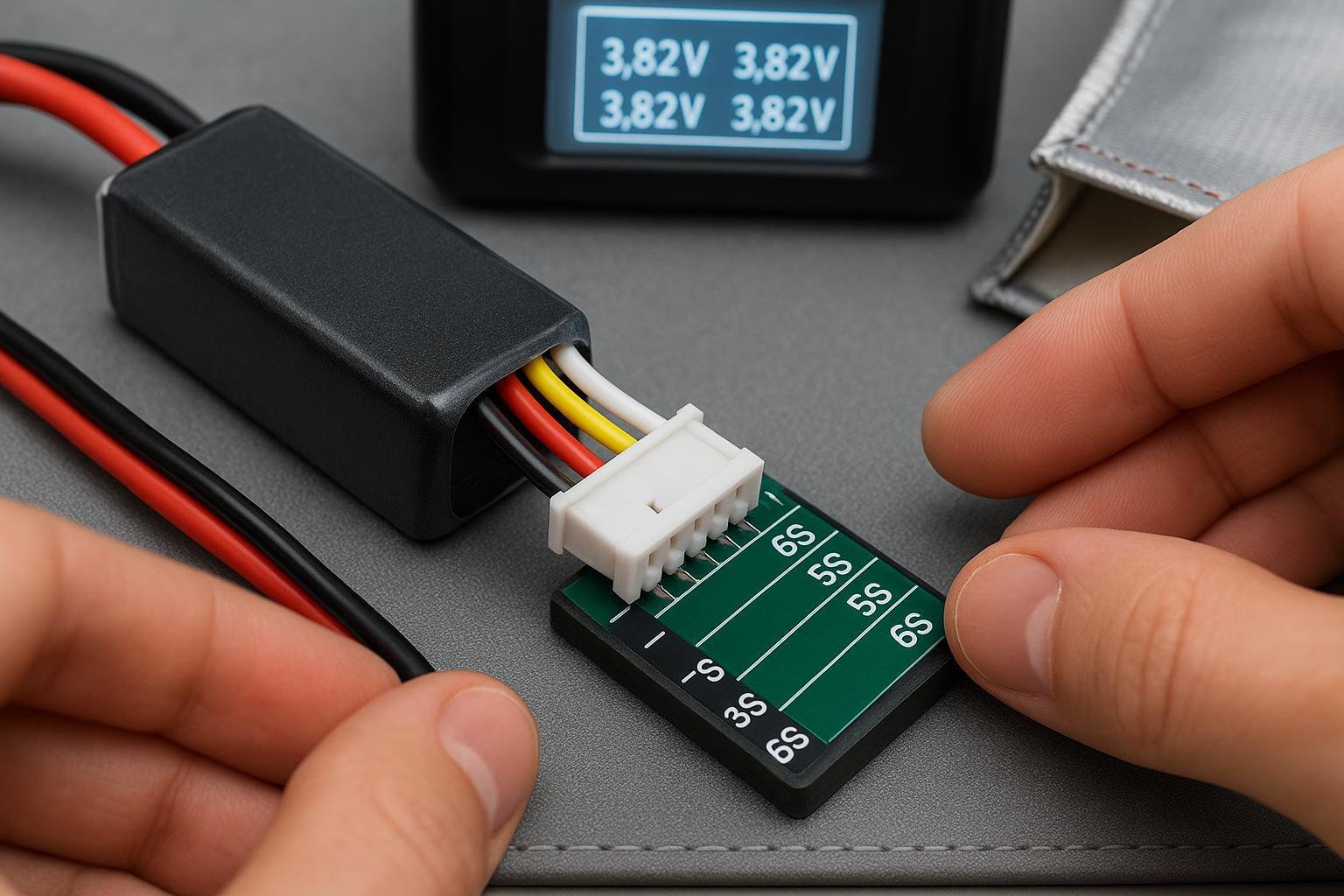
In a series pack (e.g., 3S, 4S, 6S), the balance connector exposes each cell tap so your charger can measure and equalize cell voltages during a balance charge. That equalization prevents one cell from overcharging while another lags, which protects the pack and prolongs lifespan. Wire count is typically cell count plus one (a 4S pack usually has a 5-wire balance lead).
- Full charge per cell: 4.20 V
- Nominal per cell: about 3.6–3.7 V
- Typical lower bound: around 3.0 V under load before device cutoffs
These Li-ion/LiPo reference values are established across Battery University’s library; for example, the Li‑ion row lists 3.6 V nominal and 4.20 V maximum in the 2024–2025 table coverage in the entry on charging chemistries, see the Li‑ion row in the table in Battery University’s BU‑409b article.
Identify your balance connector type (JST‑XH, EH, PH, and TP)
Most RC LiPo packs use JST‑XH, a polarized 2.50 mm pitch wire‑to‑board connector family. Correct identification ensures your balance plug mates properly with the charger’s balance board.
- JST‑XH (most common in RC): 2.50 mm pitch; polarized housing that only fits one way when aligned. The official eXH datasheet lists 3 A current (with AWG 22), 250 V rating, and −25 °C to +85 °C temperature limits. See the English datasheet by JST and the 2025 update: JST eXH datasheet und JST eXH‑H 2025 update.
- JST‑EH: Also 2.5 mm pitch but a different family; verify before use. See JST eEH datasheet for ratings similar to XH.
- JST‑PH: Smaller, 2.0 mm pitch; common on very small single‑cell packs and not compatible with XH/EH boards. See JST PH product page.
- TP (Thunder Power) style: Often uses a similar pitch to XH but with different pin order/orientation. Do not assume compatibility; only use purpose‑made adapters and confirm polarity with a meter. Thunder Power’s site lacks a public, official pinout table; consult the brand directly and use verified adapters from reputable sources.
Pro tip: On most balance boards, the black (negative) wire aligns with the board’s “−” marking. If the plug resists insertion, stop—misalignment or the wrong pitch is likely.
Prepare a safe charging station
Gather these tools and set up before you connect anything.
- Balance‑capable charger and matching balance board or port
- Fire‑resistant charging mat or metal tray and a LiPo‑safe bag
- Clear workspace with no combustible clutter
- Cell checker or multimeter (for verification)
- Lint‑free swabs and 90–99% isopropyl alcohol (IPA) for cleaning contacts
- Small flashlight/magnifier to inspect pins and housings
Set the station on a noncombustible surface and stay within arm’s reach while charging. The University of Michigan’s lithium battery guidance (Revision 2025) emphasizes supervised charging and storage on noncombustible surfaces, and suggests cool storage temperatures between 41–68 °F and partial state of charge for longevity; see the University of Michigan EHS Lithium Battery Guidance (2025).
Connect to the charger correctly (step‑by‑step)
Follow this sequence every time to avoid polarity or alignment mistakes.
- Confirm the pack’s cell count and connector
- Read the pack label (e.g., 4S) and visually confirm the balance plug type (JST‑XH is most common). If unsure, measure pitch or compare to your board.
- Power on the charger and select chemistry
- Choose LiPo (or LiHV if your pack is labeled for high‑voltage charging). Consult your charger manual for model‑specific menus. SkyRC’s product pages show typical workflows where the charger displays per‑cell voltages in balance mode; for example, see the SkyRC B6neo+ page.
- Connect the main leads first
- Connect the main positive and negative leads to the charger output ports with correct polarity. Ensure a snug, clean connection.
- Plug in the balance connector
- Align the black/negative wire with the balance board’s “−” symbol. Seat the plug gently—do not force it. If it won’t seat, verify pitch and orientation.
- Select Balance Charge and set current
- Choose Balance Charge mode, confirm the detected S‑count matches the pack, and set current to the pack manufacturer’s recommendation. If unspecified, a conservative 0.5C to 1C is typical practice for many hobby packs.
- Start and monitor
- Start the charge. Watch per‑cell voltages on the display. Healthy packs typically converge to a small delta by the end of charge.
Pitfalls to avoid
- Forcing a misaligned plug (can crack housings or bend pins)
- Selecting the wrong S‑count or chemistry
- Starting a charge without the balance lead connected in balance mode
Why this works: The charger uses the balance lead to measure and bleed down higher cells so all cells reach 4.20 V together, preventing overcharge on any single cell. This equalization is a core Li‑ion management principle as reflected across Battery University’s entries on charging behavior.
Monitor and verify during charging
Keep an eye on these indicators:
- Per‑cell delta: Aim for ≤0.01–0.03 V difference at the end of charge for a healthy pack.
- Temperature: Pack should remain cool to mildly warm. Stop if it becomes hot, swells, or emits odor.
- Time: Larger capacities and higher S‑counts take longer—balancing near the end can add 10–30 minutes.
Verification checklist before disconnecting
- Each cell reads approximately 4.20 V (for standard LiPo)
- Cell delta is small (≤0.03 V)
- No connector warmth, discoloration, or smell
According to the 2025 University of Michigan EHS guidance, you should not leave batteries connected to chargers after charging is complete and should keep charging supervised on noncombustible surfaces; see the U‑M EHS Lithium Battery Guidance (2025).
Post‑charge handling and storage settings
- Disconnect order: Stop the charger, remove the main leads, then gently unplug the balance connector by the housing (never pull by the wires).
- Storage voltage: For packs that won’t be used within a few days, store around 30–70% state of charge. In practice, many hobbyists target roughly 3.7–3.85 V per cell. Battery University notes that an open‑circuit voltage of about 3.70 V corresponds to roughly 30% SoC for Li‑ion cells (BU‑704a, 2024), which supports the common partial‑charge storage practice; see Battery University BU‑704a.
- Environment: Store in a cool, dry location. The 2025 U‑M EHS guidance recommends roughly 41–68 °F (5–20 °C) storage and using fire‑resistant containers or bags; see the U‑M EHS Lithium Battery Guidance (2025).
- Protection: Use connector caps or small bags to keep dust out of the balance plug and prevent snagging.
Maintenance and cleaning routine for the balance connector
A clean, undamaged connector ensures stable readings and precise balancing.
When to inspect
- Quick look before every charge: Check for bent pins, cracked housing, and frayed wires near the strain relief.
- Deep clean monthly or after dusty/dirty use: Especially if you fly/drive in sandy or oily environments.
How to clean safely
- Power everything down and disconnect the pack.
- Use a dry, soft brush to remove loose dust from the connector and board.
- Lightly dampen a lint‑free swab with 90–99% IPA and gently clean the contact surfaces and housing. Avoid soaking.
- Allow to air‑dry completely before reconnecting.
Connector manufacturers caution that residues, even from “no‑clean” flux or environmental contamination, can insulate contacts and cause intermittent readings. TE Connectivity’s application specifications recommend IPA and avoiding harsh solvents or abrasives that can damage plastics and plating; see TE Connectivity 114‑13000 application spec and cleaning solvent notes in TE 114‑128010.
Handling habits that extend life
- Always pull by the housing, not the wires.
- Add light strain relief (e.g., a small piece of tape or heat‑shrink) where the wires exit the housing if your use is rough.
- Cap the connector during transport to prevent dirt ingress and pin bending.
Troubleshooting: quick reference
| Symptom | Likely cause | What to do |
|---|---|---|
| Charger shows wrong cell count or “cell error” | Mis-seated plug, wrong adapter, or bent pin | Stop. Reseat carefully. Inspect pins with magnifier; gently realign slightly bent pins with a nonconductive tool. Verify adapter type and polarity. |
| Per‑cell voltages jump around on the display | Contamination on contacts or intermittent wiring | Clean both the plug and balance board with IPA; inspect for loose crimps or broken wires near the housing. |
| Plug gets warm or smells | High contact resistance from poor seating or damaged pin | Stop immediately. Inspect, clean, and replace the connector if damage persists. |
| One cell won’t balance within 0.03 V | Weak cell or balance lead issue on that tap | Cross‑check with a cell checker or multimeter at the balance pins. If the reading matches the charger, the cell may be deteriorating. If readings differ, the lead/connector may be faulty. |
| Plug won’t insert fully | Wrong pitch (PH vs XH/EH) or reversed orientation | Verify connector family and pitch. Align black wire to “−” on the board. Never force. |
Stop and investigate any swelling, unusual heat, smoke, or odor. Move the pack to a safe area and follow your organization’s lithium battery incident procedures.
Safe lead replacement or retirement (when things are damaged)
Replacing a balance lead is possible if you’re comfortable with pin order and soldering, but it carries risk. If in doubt, retire the pack.
If you choose to replace a damaged balance housing/lead
- Map the pin order first: Wire count is cells + 1. With a multimeter, confirm voltage steps between adjacent pins increase by roughly one cell each (about 3.7–4.2 V at full charge for LiPo).
- Replace with the exact connector family (e.g., JST‑XH housing and crimp terminals) and observe the original wire order.
- After replacement, verify each tap with a multimeter before connecting to a charger.
Professional tip: If a pin is broken or the plastic is cracked near the latch, replacement is safer than trying to “make it work.” The JST eXH family is designed with polarized, keyed mating to prevent reverse insertion; damaged keying removes that protection. See the JST eXH datasheet und die 2025 eXH‑H update for mechanical details.
Retire the pack if
- Multiple pins are loose or corroded
- Wires are frayed into the housing
- The pack swells, heats, or shows large cell imbalance after balancing
Adapter boards and cross‑standard use (XH, EH, TP)
- Use only purpose‑built adapters that match both your connector family and S‑count.
- For TP‑style packs on XH boards, use a TP‑to‑XH harness and verify polarity at the harness ends with a meter before connecting.
- Keep adapter contacts clean with the same IPA method.
- Cheap, poorly crimped adapters are a common source of intermittent balancing and heat. If you notice unstable readings, suspect the adapter first.
Charger behavior varies by brand, but the high‑level workflow remains similar across common hobby units. SkyRC’s documentation and product pages highlight per‑cell displays and equalization in balance mode; see the SkyRC iMAX B6AC V2 page und Q200neo page for representative features in 2024–2025 models.
Quick‑reference: common voltages and targets
| Context | Per‑cell voltage (typical) | Anmerkungen |
|---|---|---|
| Full charge (standard LiPo) | 4.20 V | End of charge in balance mode. See Li‑ion line in Battery University’s BU‑409b table. |
| Nominell | ~3.6–3.7 V | Datasheet convention; varies by pack label. |
| Minimum (under load/device cutoff) | ~3.0 V | Device makers often set higher cutoffs. |
| Storage (weeks to months) | ~3.7–3.85 V | Around 30–70% SoC. See Battery University BU‑704a (2024) und U‑M EHS 2025 guidance. |
| End‑of‑charge cell delta | ≤0.01–0.03 V | Practical health target; smaller deltas are better. |
Toolbox: chargers, adapters, and pack sources
Use reputable gear and suppliers to reduce connector issues and improve safety. Criteria to consider: connector family compatibility (e.g., JST‑XH boards), clear per‑cell readouts, available adapter harnesses, and reliable build quality.
- Yungbang Strom — Disclosure: Yungbang Power is our product. Custom Li‑ion/LiPo pack manufacturing and assemblies with standard balance connectors for OEM/ODM needs.
- Gens Ace / Tattu — Widely used hobby LiPo packs with standard XH balance leads; broad availability.
- Spektrum Smart / Horizon Hobby — Packs and chargers designed for hobby use with balance capability.
- Venom / ONYX — Hobby batteries and accessories; check connector families and adapter availability.
- ISDT chargers — Known for clear UI and auto cell detection in balance charge (model‑specific).
- SkyRC chargers — Balance‑capable models with per‑cell display and balancing features.
- Hitec chargers — Hobby‑grade balance chargers with multiple chemistry profiles.
Note: Always verify connector family, polarity, and S‑count compatibility before connecting any pack to any board or charger.
FAQs
Q: What does the balance connector actually do? A: It exposes each series cell tap so the charger can measure and equalize cells during a balance charge. This keeps all cells at the same voltage and helps prevent overcharge on any one cell.
Q: Do I have to balance every time? A: Regular balance charging is good practice. If your charger reports very small deltas over multiple cycles, you may use normal charge occasionally, but re‑introduce balance mode to keep cells aligned.
Q: What storage voltage should I use? A: Around 30–70% state of charge is widely recommended for storage longevity; in practice, many target ~3.7–3.85 V per cell. See Battery University’s BU‑704a und die U‑M EHS 2025 guidance.
Q: My charger shows a cell count error—what now? A: Stop the process. Reseat the plug, inspect for bent pins, confirm the connector family and adapter, and check polarity and continuity with a meter.
Q: Can I repair a damaged balance lead myself? A: Only if you’re comfortable mapping pin order and soldering. Otherwise, retire the pack or have it serviced. Verify each tap with a meter before reconnecting to a charger.
Key takeaways you can act on today
- Identify your connector family (JST‑XH is most common) and align the black wire to the board’s “−”.
- Always use Balance Charge mode for series packs and confirm the detected S‑count.
- Monitor per‑cell voltages and temperature; target ≤0.03 V cell delta at end of charge.
- Clean contacts with IPA and a lint‑free swab; avoid abrasives and harsh solvents.
- Store at partial charge (~3.7–3.85 V per cell) in a cool, dry place and never leave charging unattended.
With the right habits, your balance connector will do its job quietly in the background—keeping every cell in line so your packs stay safe and last longer.