

Ready to set a safe, data-driven charge current for your LiPo cells or packs? This guide shows you exactly how to choose a C-rate, configure a CC/CV charger, and verify the result—with a simple calculator you can use right now.
- Difficulty: Intermediate (you’ll read a datasheet and configure a charger)
- Time: 10–20 minutes to pick settings; charging time varies by capacity and C-rate
- Prerequisites: Your battery’s datasheet, charger/BMS specs, and a thermometer/temperature readout
- Scope: 4.2 V-per-cell Li-ion polymer chemistry (not LiFePO4 or 4.35/4.40 V variants)
What you’ll use and why
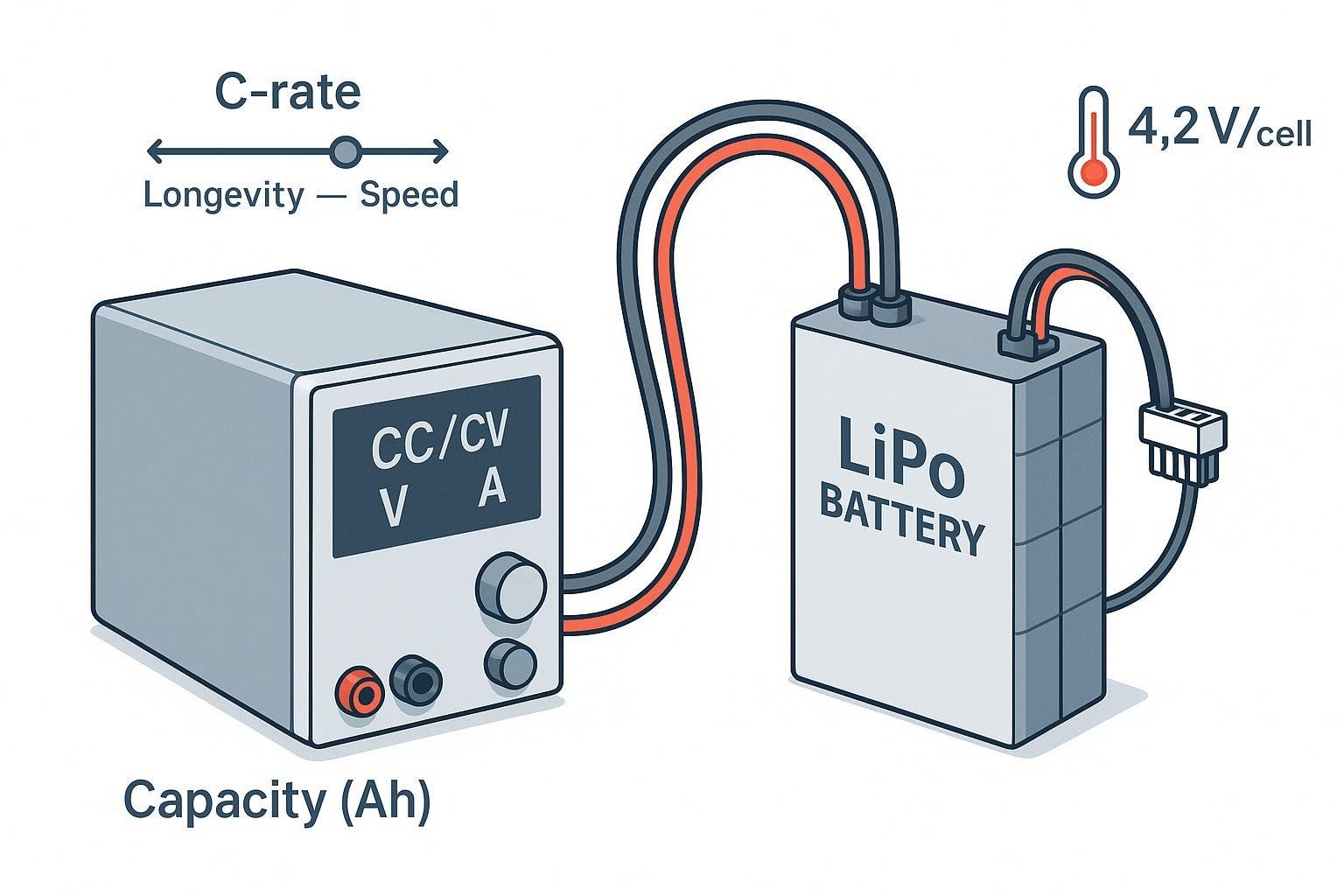
- The core formula: I_charge (A) = C_rate × Capacity (Ah)
- CC/CV profile: Constant current until the cell reaches 4.20 V, then constant voltage until current tapers to a low threshold. Precision at 4.20 V per cell matters; termination is commonly around 10% of fast-charge current according to the Texas Instruments BQ25176J datasheet (2023) and reinforced by the Power Electronics News CC/CV explainer (2022).
- Typical limits you’ll see in many recent datasheets: standard charge ≈ 0.5C and maximum ≈ 1.0C, for example in the TinyCircuits 1000 mAh LiPo datasheet (2022) and the TinyCircuits 500 mAh LiPo datasheet (2022). Always defer to your specific cell’s datasheet.
- Charging temperature window: Many Li-ion polymer datasheets specify 0–45°C for charging, such as the TinyCircuits 850 mAh (2022) spec listing 0–45°C and the TinyCircuits 18650 2500 mAh (2022) spec. Block charging outside this range unless your datasheet explicitly allows.
- Longevity vs speed: Higher charge rates raise heat and accelerate capacity fade. A 2024 open-access review reports faster degradation at 1C vs 0.2–0.5C across Li-ion chemistries; see the 2024 peer-reviewed degradation review.
Interactive LiPo charge-rate calculator
Use this logic to implement or check settings in your own spreadsheet/app. If you’re a developer, you can map these rules directly to your UI. If you’re an end user, follow the field-by-field instructions.
Inputs
- Capacity: accept mAh or Ah, normalize to Ah
- Standard charge rate (C): default 0.5C (typical; check datasheet)
- Maximum charge rate (C): default 1.0C (typical; check datasheet)
- Temperature (°C): ambient or battery temperature
- Priority: Longevity (conservative), Balanced (default), Speed (aggressive but within max)
- Pack configuration: S (cells in series), P (cells in parallel)
- Optional: Charger current limit (A)
Output fields
- Recommended C-rate and charge current (A)
- Estimated time to full: t_total ≈ t_CC + t_CV with a practical approximation t_CC ≈ 0.7 × (Capacity_Ah / I) and t_CV ≈ 0.3 × (Capacity_Ah / I). Treat this as a rule of thumb; the CV tail depends on cell and termination current, as illustrated in TI charger datasheets (e.g., BQ25620).
- Pack charge voltage target: 4.20 V × S
- Taper cutoff hint: consider full when charge current ≤ ~0.1C unless your datasheet specifies ~0.05–0.1C (per TI BQ25176J, 2023)
- Safety/status messages: temperature warnings, “check datasheet” reminder if defaults used, charger/BMS current limit note, connector/gauge reminder
Decision logic (pseudocode)
normalize Capacity_Ah
stdC = user.stdC or 0.5
maxC = user.maxC or 1.0
priority = Longevity|Balanced|Speed
temp = °C
S, P = series, parallel
I_limit = optional charger limit

// Start from a baseline
if priority == Longevity:
  targetC = min(0.5, stdC)
else if priority == Balanced:
  targetC = min(stdC, maxC)
else if priority == Speed:
  targetC = min(maxC, 1.0)

// Temperature gating and derating
if temp < 0 or temp > 45:
  block_charge = true; message = "Do not charge outside 0–45°C unless datasheet allows."
else if temp < 10 or temp > 35:
  targetC = targetC * 0.5; message += " Derated due to temperature."

I = targetC * Capacity_Ah

// Respect charger limit
if I_limit provided and I > I_limit:
  I = I_limit; message += " Capped by charger limit."

// Outputs
V_target = 4.20 * S
term_current = 0.1 * Capacity_Ah  // adjust per datasheet to 0.05–0.1C

// Time estimate (rule of thumb)
t_total_hours ≈ (Capacity_Ah / I)  // with CC/CV split ~70/30 as context
Tip: For P>1 packs built from identical cells and a proper BMS, the recommended current I applies to the overall pack. For S>1, use balance charging (external balance charger or BMS with balancing) and verify per-cell alignment at end of charge. A TI reference design triggers balancing when the inter-cell gap exceeds about 40 mV, per the TI 16s pack reference (2022).
Step-by-step: Set your LiPo charge current safely
- Gather your datasheet and limits
- Find “Standard Charge Current,” “Maximum Charge Current,” and the charging temperature window. Many modern LiPo datasheets show 0.5C standard and 1.0C max—for example, the TinyCircuits 1000 mAh (2022) sheet. If uncertain, use 0.5C and 1.0C as conservative defaults and verify with your supplier.
- Confirm pack S/P and charger/BMS capabilities
- Count cells in series (S) to compute charge voltage target: 4.20 V × S for 4.2 V chemistry. Parallel strings (P) increase capacity; current applies to the whole pack if P strings are properly paralleled via a BMS. Ensure your charger and BMS support your pack’s S/P and protections (OVP/UVP/OTP). UL notes the relevance of IEC/UL 62133-2 and UL 2054 for lithium systems; see the UL Solutions battery safety testing overview.
- Use the calculator to pick a C-rate and current
- Enter capacity, standard and max C from the datasheet, temperature, priority, S/P, and your charger’s current limit if known.
- If temp is <0°C or >45°C, do not charge unless your datasheet explicitly allows; typical LiPo specs list 0–45°C (e.g., TinyCircuits 850 mAh, 2022). If 0–10°C or 35–45°C, derate by stepping down a tier (e.g., from 1C to 0.5C).
- Set the charger: CC/CV at 4.2 V/cell
- Configure constant current to the calculated I. Set constant voltage to 4.20 V per cell with tight accuracy. The CC→CV transition occurs when the cell reaches 4.20 V, then current tapers; this is the standard profile described by the Power Electronics News CC/CV explainer (2022).
- Set termination current near 0.1C unless your cell or charger IC specifies otherwise; the TI BQ25176J (2023) defines termination at 10% of fast-charge current.
- Start charging and monitor temperature
- Keep the pack between 0–45°C. If temperature rises unusually or the pack swells, stop immediately. The NFPA’s guidance emphasizes using the correct charger and stopping if batteries are hot or damaged; see the NFPA lithium-ion safety page.
- Verify end-of-charge
- Confirm current has tapered to your termination threshold (~0.05–0.1C). Ensure per-cell voltages are closely matched at the end—within tens of mV. A TI design example uses a 40 mV delta as a balancing trigger during charging (TI 16s reference, 2022).
- Log your settings and results
- Record capacity, chosen C-rate, current, temperature, charger model/firmware, and the observed charge time. This speeds up repeatability and troubleshooting.
Worked examples (with sanity checks)
- 500 mAh single-cell at 0.5C (standard)
- Capacity = 0.5 Ah; C-rate = 0.5C → I = 0.25 A
- Estimated time ≈ Capacity/I ≈ 0.5/0.25 = 2.0 h (with CC/CV split ~1.4 h CC + ~0.6 h CV as a rough guide)
- Voltage target = 4.20 V; termination around 0.05–0.1C → 25–50 mA (check your datasheet/charger IC)
- 2000 mAh single-cell at 1.0C (max, if allowed)
- Capacity = 2.0 Ah; C-rate = 1.0C → I = 2.0 A
- Estimated time ≈ 2.0/2.0 = 1.0 h (typical; CV tail can extend slightly)
- Only use 1C if your datasheet permits; e.g., TinyCircuits 1000 mAh (2022) shows 1C max as a representative example.
- 10 Ah 3S2P pack (warm day, prioritize longevity)
- Capacity = 10 Ah; choose 0.5C or lower for longevity → I = 5 A at 0.5C
- Temperature = 36°C: derate by ~50% per our advisory; I ≈ 2.5 A
- Voltage target = 4.20 × 3 = 12.6 V; ensure balance charging or BMS balancing
- Estimated time ≈ 10/2.5 = 4.0 h (roughly; CC/CV split about 2.8 h CC + 1.2 h CV)
Verification checklist (quick pass/fail)
- Datasheet limits obeyed: current ≤ max C; voltage = 4.20 V/cell
- Temperature in range: 0–45°C; derated near extremes; blocked outside
- Termination: current tapered to ~0.05–0.1C or per datasheet/IC
- Balance: multi-cell packs finish within tens of mV per cell (e.g., <40 mV spread)
- Hardware: charger, BMS, cables, and connectors rated for the chosen current; no hot spots
- Behavior: no swelling, hiss, or odor; stop immediately if observed (see NFPA lithium-ion basics)
Troubleshooting: If something looks off
Charge never finishes (stuck in CV for hours)
- Check termination threshold (some chargers default to very low mA). If set too low relative to I, CV can run excessively long. Verify CC current is actually achieved (charger limit?) and that temperature gates aren’t throttling.
Battery gets hot
- Reduce C-rate; verify ambient; check connectors/cable gauge. High resistance causes heat. Ensure the charger’s voltage accuracy at 4.20 V/cell is within spec, as emphasized in the Power Electronics News CC/CV explainer (2022).
Pack imbalance grows during charge
- Use balance charging; confirm BMS balancing is active. A TI design triggers balancing once inter-cell gap exceeds ~40 mV (TI 16s reference, 2022). Replace or service packs that remain imbalanced.
Can I charge below 0°C at a reduced current?
- Not unless your datasheet explicitly allows it and your BMS/charger supports low-temp charging. A UL Q&A emphasizes stopping charge outside specified temperature ranges; see the UL engineer Q&A page.
Safety and standards context (short)
- For product designs, many organizations evaluate against IEC/UL 62133-2 and UL 2054; see the UL Solutions battery safety testing overview. These standards, alongside transport testing like UN 38.3, frame safe charging and pack protections.
Toolbox: Suppliers and resources (neutral)
Disclosure: Yungbang Power is our product.
- Yungbang Power(永邦电源) — LiPo/Li-ion packs with customization and certification support; datasheet-driven design and OEM/ODM supply readiness.
- EEMB Battery — Broad catalog of Li-ion polymer cells and packs with accessible datasheets and customization.
- Jauch Battery — Engineering-focused supplier; detailed specs and certification guidance for custom packs.
- Smart chargers: Consider reputable balance chargers and charger IC ecosystems (e.g., TI BQ series) with precise 4.20 V regulation and configurable termination (see TI BQ25620 datasheet).
FAQ
What if I don’t have a datasheet?
- Use 0.5C as a conservative standard and 1.0C as a provisional max for 4.2 V-per-cell LiPo, but confirm with your supplier as soon as possible. Examples of 0.5C/1C defaults appear in 2022 LiPo datasheets such as TinyCircuits 500 mAh.
Does this apply to LiFePO4 or high-voltage Li-ion (4.35/4.40 V)?
- No. Those chemistries use different CV voltages and sometimes different current/temperature rules. Always use chemistry-specific datasheets and charger settings.
Is 70/30 CC/CV time split exact?
- No—treat it as a planning heuristic. Actual CV tail depends on the termination threshold and the cell. TI charger datasheets illustrate the phase behavior, but the exact percentages vary.
Key formulas recap
- I (A) = C_rate × Capacity (Ah)
- Pack charge voltage (V) = 4.20 × S (for 4.2 V LiPo chemistry)
- Typical termination current ≈ 0.05–0.1C (datasheet/IC dependent)
Set your charger with care, verify with measurements, and you’ll have a safe, repeatable charging setup that matches your goals for speed and longevity.