

A Battery Management System (BMS) is the brain and safety layer of any lithium battery pack. It monitors cells, protects against abuse, balances differences between cells, estimates state of charge/health, and communicates with the rest of the device or vehicle. If you design, procure, or certify products with lithium batteries, understanding BMS functions isn’t optional—it’s central to safety, reliability, and go‑to‑market readiness.
In my experience, the biggest delays in launch come from unclear protection strategies, under‑specified communication interfaces, and late discovery of compliance gaps. This guide brings you from fundamentals to practical decisions: how protection mechanisms work, passive versus active balancing, SOC/SOH estimation methods, protocol selection, architecture trade‑offs, and how international standards shape your design and documentation.
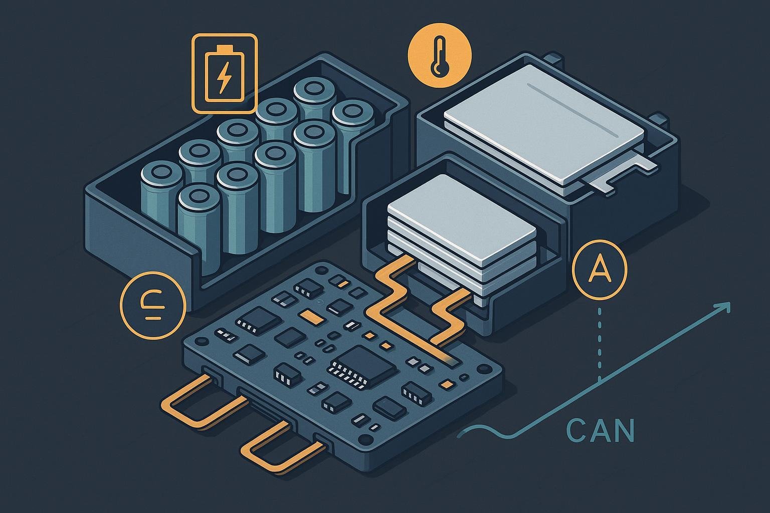
What the BMS does—and why it matters
At a high level, a BMS:
- Monitors cell and pack voltages, currents, and temperatures
- Enforces safe operating limits (charge/discharge voltage/current, temperature)
- Balances cells to maintain uniformity
- Estimates state of charge (SOC) and state of health (SOH)
- Logs and reports status, faults, and telemetry via communication buses
- Coordinates with chargers, power converters, and system controllers
Without a well‑implemented BMS, lithium batteries are far more likely to experience accelerated aging, performance drift, and—in worst cases—hazardous events. The BMS is both a protective device and a data source that enables smart control and serviceability.
Pack hierarchy and where the BMS fits
Battery packs are typically organized as:
- Cells (pouch, prismatic, cylindrical)
- Modules (groupings of cells)
- Pack (modules with harnessing, contactors, fuses, and enclosure)
BMS hardware and firmware sit across this hierarchy. In smaller packs, a centralized controller monitors all cells. In larger systems, distributed monitors at each module chain to a master controller. Monitors/AFE ICs measure cell voltages and temperatures, while the main controller executes algorithms, commands contactors/MOSFETs, and manages communications.
Protection functions: how the BMS prevents damage and hazards
Protection is the BMS’s first job. Here’s how core mechanisms work in practice:
Overvoltage (OV) and Undervoltage (UV): When any cell approaches upper/lower voltage limits, the BMS reduces or stops charge/discharge to avoid lithium plating or over‑discharge damage. AFEs typically supervise cells and drive MOSFETs/contactors to open or close.
Overcurrent (OCP) and Short‑circuit Protection (SCP): The BMS detects abnormal charge/discharge currents (or external shorts) and responds by opening contactors or MOSFETs, logging the fault and signaling upstream controllers.
Overtemperature (OTP) and Undertemperature (UTP): Using NTCs or IC temperature sensors, the BMS enforces thermal windows and may derate power or disallow charging in cold/hot conditions.
Pre‑charge and inrush control: Connecting a pack to a DC link with large capacitors can cause damaging inrush. A pre‑charge path (resistor plus controlled sequencing) safely charges the DC link before closing main contactors. For a typical topology and timing considerations, see the Texas Instruments design idea in the TI High‑Voltage Precharge note (2024).
Reverse polarity and open‑wire detection: Good designs protect against wiring errors and detect broken conductors. Automotive/industrial‑class monitors document open‑wire diagnostics and daisy‑chain integrity, such as the capabilities described in the Analog Devices ADBMS6830B datasheet (2024).
These mechanisms must be tuned to your cells, pack architecture, and application. Avoid copying thresholds blindly—coordinate with the cell manufacturer’s specifications, your charger profile, and environmental conditions.
Cell balancing: passive vs. active
Cell balancing preserves uniformity so that all series cells share charge/discharge evenly. Two main approaches are used:
Passive balancing: Bleeds charge from higher‑voltage cells through resistors, dissipating energy as heat. It’s simple and cost‑effective for small or well‑matched packs. Thermal design matters because balancing currents (often tens to hundreds of milliamps) convert directly to heat.
Active balancing: Transfers energy from high‑SOC cells to low‑SOC cells via capacitive/inductive or DC‑DC methods. It’s more efficient and helps keep large packs tighter in SOC, but increases BOM and control complexity. A 2025 peer‑reviewed study reports improved SOC uniformity and potential lifespan benefits with active strategies; see the Scientific Reports UKBF/active balancing work (2025).
Your choice depends on pack size, cell matching quality, thermal budget, and cost. For consumer devices and small mobility, passive may suffice; for EV/industrial ESS, active balancing can pay for itself in performance consistency and serviceability.
SOC and SOH estimation: methods and trade‑offs
A production BMS typically uses hybrid estimation. The building blocks are:
Coulomb counting: Integrates current over time for fast, real‑time SOC tracking. It drifts and needs periodic recalibration.
Open‑circuit voltage (OCV) models: Map rested voltage to SOC. Useful for calibration checks, but sensitive to temperature and aging and requires rest conditions.
Model‑based filters (EKF/UKF): Fuse measurements with a battery model (e.g., Thevenin 1RC/2RC) to correct drift and capture dynamics. A 2024 study demonstrates enhanced SOC estimation via hybrid filtering; see Scientific Reports SOC estimation (2024). UKBF/UKF approaches continue to show promise in non‑linear regimes.
Impedance‑based SOH: Track degradation via impedance/frequency response (EIS or time‑domain equivalents). Many systems run limited diagnostics online; deeper sweeps are often offline. For broader context, see the J. Electrochem. Sci. Technol. SOP review (2024).
Data quality and operating conditions drive accuracy. For embedded feasibility, fusing coulomb counting with occasional OCV calibration and a tuned EKF/UKF provides robust results for many applications. When considering ML estimators, validate across representative duty cycles and temperatures and retain interpretability for safety cases.
BMS architecture choices: centralized, distributed, modular
Centralized: One controller and AFE set monitors all cells. Pros: simple, low cost; good for small/medium packs. Cons: long harnesses raise EMC and measurement fidelity concerns; single point of failure.
Distributed: Module‑level monitors daisy‑chain to a master (iso‑SPI, CAN, etc.). Pros: scalability, shorter harnesses, better measurement integrity. Cons: higher complexity, careful EMC/isolation required. Many industrial/automotive monitors and evaluation boards support daisy‑chain topologies; as an example class, see industrial monitors like ADBMS series in the Analog Devices ADBMS6830B datasheet (2024) for daisy‑chain diagnostics and isolation considerations.
Modular: Each module includes its own local BMS; systems scale by adding modules and coordinating at a higher level. Pros: serviceability and reliability; often aligns with functional safety partitioning. Cons: greater cost and integration complexity.
Choose based on pack size, service strategy, reliability targets, and available integration resources.
Communications and diagnostics: choosing the right bus
Communication is how the BMS collaborates with chargers, power converters, and host systems, and how diagnostics and updates are delivered. Here’s how major options compare:
CAN and CAN FD (ISO 11898): Classical CAN offers robust error detection with up to 1 Mbit/s and strong EMI tolerance; CAN FD increases payload (up to 64 bytes) and higher data rates in the data phase. 2024 updates maintain relevance for automotive and industrial integration; see the CiA note referencing ISO 11898‑2:2024 physical layer and the ISO 11898‑1:2024 protocol release. Diagnostic stacks like UDS (ISO 14229) and profiles like J1939 ride on CAN for fault codes, telemetry, and flashing.
SMBus/PMBus (Smart Battery): SMBus is the standard for many smart batteries, exposing voltage, current, temperature, SOC/SOH, alarms, and charging negotiation. For canonical definitions and commands, use the SMBus 3.3.1 specification (2024). For integration examples, Texas Instruments’ Smart Battery via SMBus app note (2024) shows MCU‑mediated charging with SMBus command flows. PMBus extends SMBus in power systems and can complement battery management at rack or converter level.
RS‑485/Modbus: Differential, robust for long cable runs and noisy environments, common in stationary ESS and industrial systems. Typical deployments range from low tens of kbps up to hundreds of kbps, with simple master‑slave framing and widespread tooling.
UART/I2C: Simple and low cost for short distances or internal board communications. Not ideal for noisy environments or safety‑critical external links without additional protections.
Selection criteria:
- Environment/EMI and cable length
- Required bandwidth and payload size
- Diagnostic ecosystem (UDS/J1939 for CAN; SBS/alerts for SMBus)
- Topology (point‑to‑point vs multi‑drop vs daisy‑chain)
- Service tooling and field update needs
A practical pattern: Automotive EV/HEV—CAN FD primary; industrial ESS/robotics—RS‑485/Modbus or CAN; smart batteries—SMBus/SBS; local embedded—UART/I2C.
Typical BMS components and design notes
Cell monitors/AFEs: Measure cell voltages and temperatures; provide balancing drivers and diagnostics (open‑wire, CRC). Industrial/automotive‑grade parts also support isolated daisy‑chains.
Controller/MCU: Runs protection logic, balancing control, SOC/SOH estimation, communication stacks, and logging.
Current sensing: Shunt (high accuracy, needs thermal consideration) or Hall‑effect (isolated, lower insertion loss). Choose based on range, efficiency, and isolation needs.
Power switches: MOSFETs for small/medium packs; contactors for high current/voltage systems.
Temperature sensing: NTCs or digital sensors placed near high‑risk cells and thermal interfaces; ensure good thermal coupling.
Power supply and isolation: Stable rails and appropriate isolation for distributed systems and noisy environments.
Harnessing/layout and EMC: Short, shielded sensing lines; thoughtful ground and return paths; filtering for communication buses.
Compliance landscape: transport and product safety
Compliance dictates design decisions and documentation—and determines whether you can ship. The most commonly encountered frameworks are:
UN Manual of Tests and Criteria, Part III, Subsection 38.3 (UN 38.3): Transport safety tests ensure cells/batteries withstand altitude, thermal cycling, vibration, shock, external short circuit, impact/crush (cells), overcharge, and forced discharge without fire, explosion, or leakage. Access the official manual via the UNECE UN Manual Rev.8 page (2023).
IATA Lithium Battery Guidance (2025): For air cargo, IATA reiterates UN 38.3 requirements and provides packaging instructions and SOC guidance. The 2025 guidance document describes conditions under which SOC limits apply (e.g., batteries shipped with/inside equipment), and notes the transition toward mandatory SOC ≤ 30% for certain instructions starting Jan 1, 2026—teams must confirm the exact DGR packing instructions that apply to their shipment. See the IATA Lithium Battery Guidance Document (2025).
PHMSA Lithium Battery Test Summary (TS) (2024): Shippers must make a UN 38.3 test summary available upon request, containing specific fields (manufacturer/test lab, report ID/date, battery description, tests and outcomes, edition references, responsible person). The official template guidance is the PHMSA Test Summary PDF (2024).
IEC 62133‑2 and UL 2054: IEC 62133‑2 defines safety requirements for portable sealed secondary lithium cells/batteries, widely used in consumer/industrial products. UL 2054 addresses household/commercial battery safety for primary and secondary chemistries in North America. Refer to the IEC site (62133‑2 listing) via the Webstore search, and the UL Standards Shop (UL 2054) for purchase/info.
ISO 26262 (Road vehicles—Functional safety): For automotive, the BMS is part of the electrical/electronic item requiring hazard analysis and ASIL allocation, with lifecycle processes for safety goals, architecture, and validation. See the ISO site overview for official materials.
Note: Standards are updated periodically. Engage your compliance lab early to confirm editions and national adoptions relevant to your markets.
UN 38.3 testing workflow and readiness checklist
A typical test program looks like this (your lab may vary):
- Technical intake: Define cell/battery variants, state of charge, and configuration per UN 38.3.3.
- Execute T.1–T.8 sequences on prescribed samples, recording pass/fail, inspections, and electrical behavior.
- Compile the full test report and provide a Test Summary (TS) per PHMSA/Model Regulations. Ensure retrieval on request for shipments.
- Plan for retests if any sample fails; allocate schedule buffers.
Pre‑compliance readiness checklist:
- Confirm your exact shipping configuration (cells vs batteries; with/inside equipment) and applicable IATA packing instructions.
- Gather prior test data for similar designs where available.
- Validate pre‑charge and protection sequencing under worst‑case inrush and fault injection (the TI precharge note (2024) illustrates concepts to review).
- Prepare labeling/marking, MSDS/SDS, and handling instructions consistent with regulations.
- Draft the TS with all required fields and contacts; cross‑check against the PHMSA TS guidance (2024).
For overall process context and timelines from a testing provider perspective, see Intertek’s program overview (high‑level) on UN 38.3 testing; consult your chosen lab for specifics.
Troubleshooting and common failure modes
Contactor welding or premature wear due to improper pre‑charge sequencing: Use verified sequencing and monitor dV/dt/current before closing main contactors; validate with worst‑case converter capacitance and temperatures. The TI precharge design idea (2024) shows typical protections.
Sensor drift leading to SOC misreporting: Combine coulomb counting with periodic OCV checks and model‑based filtering; the 2024 SOC estimation study demonstrates hybrid benefits.
Harness faults (open‑wire): Choose AFEs with open‑wire diagnostics and run periodic line integrity checks. Industrial AFE datasheets such as the ADBMS6830B (2024) describe detection strategies.
Thermal non‑uniformity: Add sufficient sensors and ensure good thermal coupling to cells and heat paths. Implement derating when any sensor approaches thresholds.
Communication bus reliability issues: If you experience noise‑induced errors, consider moving from UART/I2C to differential buses (CAN or RS‑485), adjust termination/shielding, and review grounding.
Implementation roadmap (from requirements to launch)
- Requirements and risk analysis: Define electrical limits, thermal envelope, cycle life targets, and functional safety needs. For automotive programs, align with ISO 26262 lifecycle expectations.
- Architecture selection: Centralized vs distributed vs modular; select AFEs/monitors and communication buses.
- Prototype and bench validation: Verify protection (OV/UV/OCP/OTP/SCP), balancing, SOC/SOH estimation, and communication robustness under EMI and temperature extremes.
- Firmware and diagnostics: Implement fault codes, freeze‑frame logging, and service diagnostics. For automotive, UDS on CAN and field update flows are standard; for smart batteries, implement SBS/SMBus commands per the SMBus 3.3.1 spec (2024) and integration patterns like those in TI’s SMBus app note (2024).
- Pre‑compliance testing: Run transport safety (UN 38.3) and product safety (IEC 62133‑2, UL 2054) with your lab; confirm editions and market adoptions via the UNECE UN Manual Rev.8 page (2023), IATA guidance (2025), IEC Webstore, and UL Standards Shop.
- DVT/PVT and operations handoff: Finalize documentation, TS availability, labeling, and field service tools. Train support teams on diagnostics and safe handling.
Vendor selection criteria (neutral and practical)
When evaluating BMS vendors or battery pack partners, focus on:
- Compliance track record and test documentation completeness
- Communication protocol support (CAN/FD, SMBus/PMBus, RS‑485/Modbus) and diagnostic tooling
- Quality systems (ISO 9001/14001) and traceability
- Scalability (from prototypes to mass production), and after‑sales support for logging/updates
- Ability to customize balancing strategy, thermal sensing, and enclosure/harnessing for your use case
Next steps
If you’re planning a new product or an upgrade, map your requirements against the sections above and engage a qualified battery systems partner early—especially for compliance planning and protocol integration.
Disclosure: Yungbang Power is our product. A partner like Yungbang Power supports custom lithium packs with integrated BMS, compliance‑minded design, and scalable manufacturing. As with any vendor, evaluate using the criteria above and request representative test reports and communication protocol demonstrations.
References and primary sources (selected)
- Precharge/inrush protection topology and timing: TI High‑Voltage Passive Precharge With Overcurrent Protection (2024)
- Industrial/automotive monitor and diagnostics (open‑wire, balancing): Analog Devices ADBMS6830B datasheet (2024)
- Active balancing benefits in large packs: Scientific Reports UKBF/active balancing (2025)
- Hybrid SOC estimation improvements: Scientific Reports SOC estimation (2024)
- SOH/SOP context and robustness: J. Electrochem. Sci. Technol. review (2024)
- CAN updates and references: CiA on ISO 11898‑2:2024, CiA news on ISO 11898‑1:2024
- Smart Battery communications: SMBus 3.3.1 spec (2024), TI Smart Battery over SMBus app note (2024)
- Transport safety and air cargo guidance: UNECE UN Manual Rev.8 (2023), IATA Lithium Battery Guidance (2025)
- Test summary requirements: PHMSA Lithium Battery Test Summary (2024)
- Product safety standards access: IEC Webstore/62133‑2, UL Standards Shop/2054
- Functional safety context: ISO site overview