

Integrating lithium battery plates (busbars) with a Battery Management System (BMS) is where real-world performance is won or lost. In practice, the interface defines measurement fidelity, protection reliability, balancing efficiency, and certification outcomes. Based on multi-market integration work since 2013, here’s a pragmatic, standards-aware guide you can apply immediately.
1) What the Plate↔BMS Interface Actually Does
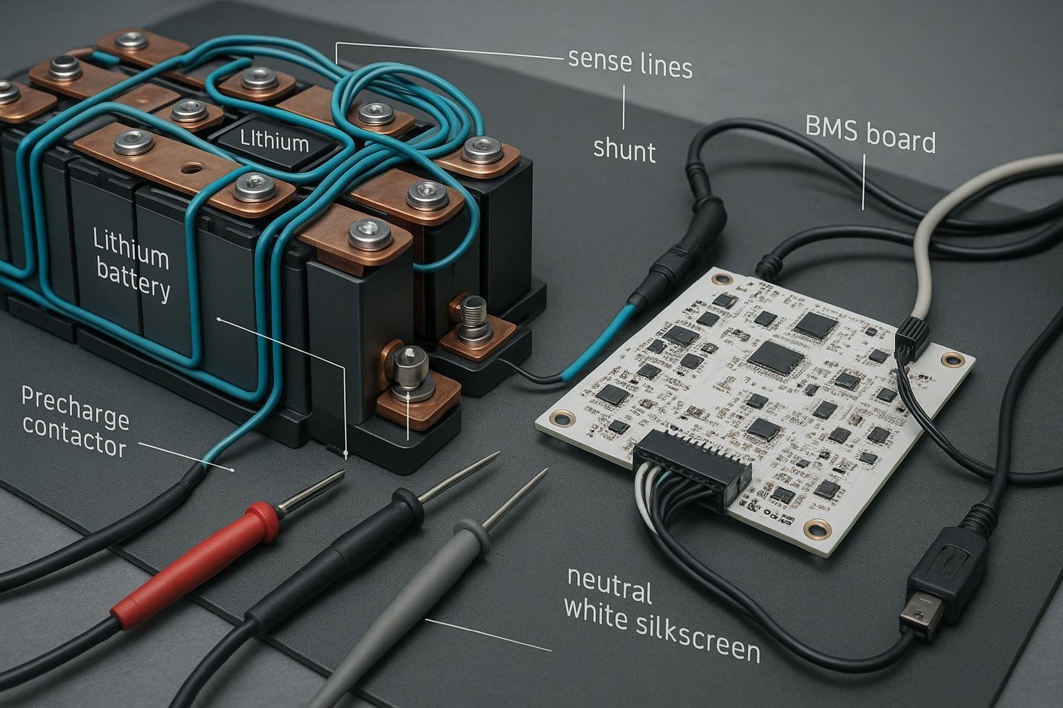
At pack level, copper plates or busbars tie cells into series/parallel groups. The BMS connects to this network primarily through:
- Sense taps per cell junction to measure voltages and enable balancing.
- A current sensor (shunt or Hall-effect) in the main return or supply path.
- MOSFETs/contactors that enforce charge/discharge, precharge, and fault isolation.
- Thermal sensors mounted at terminals/busbars to monitor hotspots.
Done right, this yields stable measurements, predictable protections, and repeatable certification results. Done wrong, you get open-wire faults, false trips, thermal runaway risk, and EMI-induced chaos.
2) Hardware Interface Best Practices
2.1 Sense Wiring and Protection
Map taps sequentially from pack negative (B−) across each cell junction up to pack positive (B+). Verify the mapping before any power-up by measuring each junction against B− with a meter; this mirrors the harnessing methods in the Orion BMS manuals, which detail cell tap routing and pinouts for safe interfacing per their wiring guidance in the 2025 editions of the Orion BMS2 and Jr2 manuals. Reference: Orion BMS2 Wiring Manual and Orion Jr2 Wiring Manual.
Add per-line series resistance and RC filtering to protect the BMS inputs and curb high-frequency noise. Texas Instruments’ ESD-compliant example for the BQ769xx family used around 20 Ω series resistors and 220 nF capacitors to ground on each cell input, values shown in a 2024 test board report that passed IEC 61000-4-2 ESD. See the specific numbers in the BQ76942 ESD test report (TI, 2024). Analog Devices guidance for the LTC681x family typically shows around 10 Ω in series and 10–100 nF shunt capacitors; details are discussed in ADI’s 2020 analysis of open-wire detection in the LTC681x line: ADI “Deeper Look into Open Wire Detection”.
Protect against hot-plug and transients with low-leakage TVS/diodes on sense inputs. Consult vendor app notes; ADI’s DC2100B user guide for LTC3300 balancing references protection devices and cautions on leakage and clamping: ADI DC2100B user guide (2019).
Routing discipline: twist sense pairs, keep them away from high-current paths, minimize length and connector count, and keep harness lengths consistent to prevent offset errors. Orion manuals provide pragmatic routing and fusing guidance; see the wiring sections in the Orion BMS2 Manual (2025).
Verify open-wire diagnostics in firmware. The LTC681x devices include built-in tests that flag breaks; ADI’s article above explains detection nuances and conditions.
2.2 Balancing: Passive vs. Active
Passive balancing bleeds excess charge through resistors. It is simple and inexpensive, but it wastes energy as heat and is limited in current. Device examples often specify tens to a few hundred milliamps; Texas Instruments’ BQ76PL455A shows around 56 mA at 4.2 V in typical configurations per the 2020 datasheet: TI BQ76PL455A datasheet. For conceptual background, Battery University’s 2022 overview summarizes trade-offs: Battery University BU-803a.
Active balancing moves charge between cells using inductors/transformers or switched capacitors. It can achieve amp-level currents and high efficiency, shortening equalization time and preserving energy. The LTC3300-1, a bidirectional flyback balancer, reaches up to the order of 10 A when designed with appropriate magnetics and MOSFETs, and efficiencies reported near 92% in Analog Devices’ documentation and demo materials: see the ADI DC2100B user guide. Note chemistry applicability; capacitor-based balancers like the LTC3305 target lead-acid stacks and are usually not selected for Li-ion packs: LTC3305 datasheet.
Practical choice: Below ~2–3 mV/cell/month drift and modest pack sizes, passive is often sufficient and simpler. For larger EV/industrial packs with frequent high-rate cycling or wide temperature gradients, active balancing can reduce balancing windows and heat. Factor EMI complexity and cost when deciding.
2.3 Current Sensing
Shunt sensing with 4-wire Kelvin connections is the workhorse for precision. Place the shunt where layout is compact and thermal gradients are low; minimize loop area. Consider high-side vs low-side trade-offs: high-side keeps the load referenced to ground but complicates measurement; low-side is simpler but can make ground bounce an issue. Analog Devices’ app notes and Orion documentation outline best practices. See ADI AN-105 collection and the current sensor sections in the Orion BMS2 manual.
Hall-effect sensors avoid insertion loss and can be simpler to retrofit, but check offset drift vs temperature and ensure adequate bandwidth and linearity for your protection logic.
2.4 MOSFET Switching and Contactors
Use back-to-back MOSFETs to block in both directions when off. Many designs split charge and discharge paths with separate FET stacks for finer control. Paralleling FETs requires gate damping and attention to current sharing. TI’s parallel FET guidance (2021) details stability considerations: TI SLYP856.
Integrate a precharge path to limit inrush to the DC link before closing the main contactor. Most packs switch the positive line and control coils via a DC-DC converter that provides appropriate coil voltage. Orion’s manuals include pinouts and precharge control details: Orion BMS2 Wiring Manual and Orion Jr2 Wiring Manual.
2.5 Thermal Sensing on Plates/Busbars
Sensor selection: 10 kΩ NTC thermistors with Beta around 3950 K are common for terminal/busbar monitoring, with ±1% tolerance parts available and thermal time constants in the ~10 s range in typical mounting. For an overview of battery terminal NTC use cases, see Ametherm’s 2023 technical note: Ametherm battery terminal NTC overview.
Placement: position near cell terminals and busbar hotspots. Use ring lugs, spring clips, or thermally conductive epoxy. Ensure dielectric insulation and robust strain relief; Teflon-coated leads reduce abrasion risk. For general mounting practices and electrical safety considerations, see Altium resources on NTC use.
Sensor counts: one per cell for compact modules, or at least one per two cells plus a few busbar hotspots for larger modules. UNECE R100 thermal criteria, updated through 2024, imply coverage sufficient to monitor gradients; design for <4–5°C gradient in normal operation and ensure test compliance.
2.6 EMI/ESD Mitigation
- Route signal lines away from high-current loops, twist pairs, add common-mode ferrites where needed, and minimize connector tail lengths. TI’s EMI-safe battery pack design guide (2018) provides layout and filtering practices applicable to pack harnesses and BMS PCBs: TI SLUA776.
3) Software, Algorithms, and Communications
3.1 SOC/SOH Estimation and Calibration
Stack methods: combine coulomb counting with OCV-based relaxation checks and temperature compensation. Extended Kalman Filter (EKF) implementations reported in peer-reviewed 2024–2025 literature show <2% SOC error under controlled conditions on hardware-in-the-loop rigs; for example, a 2025 engineering study demonstrates EKF-based SOC achieving sub-2% errors across varying temperature ranges on lab benches with calibrated instrumentation: see the PMC EKF hardware implementation (2025).
Calibration cadence: smart battery practices suggest periodic calibration when usage patterns drift; Battery University’s 2024 guidance recommends occasional full charge/discharge cycles to recalibrate impedance-tracking algorithms when accuracy degrades: Battery University BU-605.
3.2 Communications and Logging
Protocols: CAN (ISO 11898) with application layers like J1939 for heavy-duty equipment; SMBus for portable devices. Define message sets for SOC/SOH, cell voltages, temperatures, alarms, and balancing status. Use CRC/checksums, manage wake/sleep, and implement timeouts for critical commands.
Logging: Record telemetry at 1–10 Hz for diagnostics; store event logs for faults and calibration actions in non-volatile memory with cyclic overwrite to preserve recent history. Orion manuals detail CAN wiring and diagnostic logging practices in typical BMS deployments, which you can model as a baseline.
4) Engineering Workflow: EVT → DVT → PVT
A disciplined workflow minimizes late-stage surprises and certification rework.
Schematic and safety review
- Include per-tap series resistors, RC filters, and TVS/diodes; confirm creepage/clearance and isolation per intended standards (UL/IEC). UL service overviews describe battery pack testing scopes for EV and non-automotive products; start with requirements for UL 2580 (EV) or UL 2054/2271 (consumer/LEV): UL battery module and pack testing overview (2024).
Harness and busbar design
- Select conductor gauge for current and thermal rise; prefer tin-plated copper busbars. Define weld/joint quality criteria and micro-ohm measurement plans. Hioki’s manufacturing guides explain sub-milliohm joint verification with 4-wire instruments like RM3545: Hioki RM3545 (manufacturing page, 2023).
Firmware setup
- Protection thresholds, balancing strategy (passive/active), SOC/SOH parameters, logging rates, and communication timeouts. Document default and extreme conditions.
Fixture and HIL testing
- Emulate NTC/PTC sensors, inject faults (open-wire, shorts, overtemp), verify communication robustness, and stress timing. TI’s EMI/ESD pack design guide provides test hints relevant to layout-induced faults: TI SLUA776.
EVT validation
- Verify electrical protections (over/under-voltage, short-circuit), thermal sensor coverage and gradient checks, mechanical integrity (vibration/shock), and EMI/ESD pretests.
DVT and transport pre-compliance
- Align to IEC safety (portable: IEC 62133‑2; industrial: IEC 62619). Prepare for UN 38.3 transport testing (T1–T8 sequences) and reference the official UNECE manual (Rev.7, 2020 edition still current in 2025): UN Manual of Tests and Criteria, Section 38.3.
PVT and certification documentation
- Finalize production test plans, traceability packs (firmware versions, calibration logs, fault histories), and compliance mapping artifacts. UL’s EV battery testing overview explains documentation expectations for certification projects: UL EV battery testing & compliance (2024).
Pass/fail examples: UNECE R100 updates (Rev.3, 2024) include thermal propagation and gradient criteria. Practical design targets are <4°C gradient over defined test durations and robust fault containment; see UNECE Regulation No. 100 Rev.3 (2024).
5) Example Integration Workflow (Product Methods)
[Disclosure: The following example references our own engineering workflow at Yungbang Power.] Integrators frequently ask how we structure a plate↔BMS interface validation. At Yungbang Power, a typical 12s2p consumer/industrial pack goes through:
- Harness design with per-tap 15–22 Ω series resistors and 100–220 nF RC filters based on target IC; twisted pairs and connector strain relief per Orion-style routing discipline.
- Passive balancing configured at 100–150 mA per cell for compact modules; active balancing reserved for larger industrial packs where efficiency and equalization time justify complexity.
- Shunt placement on the low-side with 4-wire Kelvin, paired with a secondary Hall sensor for redundancy on high-current products.
- Thermal sensing using 10 kΩ NTCs at each end-of-string and two busbar hotspots; firmware thresholds tuned after EVT thermal mapping.
- Precharge control validated with a DC link emulator; gate damping verified on parallel FET stacks.
- EVT→DVT gates tied to micro-ohm weld limits (<0.1 mΩ) and UN 38.3 pre-tests completed before pilot runs.
This example is illustrative, not prescriptive; adapt values to your IC and certification scope.
6) Troubleshooting and Failure Modes
Open sense line: The BMS reports missing/erratic cell voltages; devices like LTC681x throw open-wire diagnostics. Automotive service references describe equivalent alerts (e.g., BMS_w107/BMS_f107 for open voltage sense harness). A 2023 teardown guide explains the symptom set and resolution paths for such codes in practice.
High contact resistance at busbar joints: Symptoms include localized heating, voltage drops under load, and persistent imbalance. Measure joint resistance with a 4-wire micro-ohm meter; targets at or below ~0.1 mΩ are common acceptance thresholds in production per Hioki’s manufacturing notes.
EMI-induced misreads: Erratic sensor values or false trips during high-current events indicate routing/shielding issues. Review harness separation, add ferrites, and verify ground references per TI SLUA776 practices.
Diagnostic workflow:
- Visual inspection of connectors, harnesses, strain relief, and corrosion.
- Electrical verification of each tap against B− with a handheld meter; compare against BMS readings.
- Micro-ohm measurement of critical welds/joints; rework above-threshold joints.
- Communication isolation tests: disconnect other CAN devices, verify termination, and remove long stubs.
7) Quantitative Benchmarks to Guide Decisions
- Passive balancing: ~50–250 mA typical; example 56 mA at 4.2 V for TI BQ76PL455A.
- Active balancing: up to ~10 A for LTC3300-class flyback designs with ~92% efficiency when designed correctly.
- Sense line protection: series resistors around 10–20 Ω; shunt capacitors 10–220 nF depending on IC guidance.
- Busbar/weld resistance: aim for micro-ohm to sub-milliohm; production acceptance often ≤0.1 mΩ per critical joint.
- Thermal gradients: design to keep modules within <5°C in operation; plan for UNECE R100 criteria of <4°C in specific tests.
These numbers are not absolutes—consult your IC datasheets, test results, and certification scope—but they are reliable starting points.
8) Compliance Mapping Essentials
Early in design, map your target standards and build artifacts accordingly:
- UL 2054 for consumer/commercial packs; UL 2271 for LEV; UL 2580 for automotive EV — determine your category before schematic freeze. Overviews and service pages clarify scopes: see UL’s battery pack testing pages for EV and general products.
- IEC 62133-2 (portable) and IEC 62619 (industrial) drive many safety test parameters; the official IEC webstore pages enumerate required tests and applicability: IEC 62133-2 (2017) and IEC 62619 (2022).
- Transport: UN 38.3 is mandatory for air/sea/road shipment; align your DVT pre-tests with the UNECE manual: UN 38.3 manual (Rev.7, 2020).
- Automotive system safety: UNECE Regulation No. 100 (Rev.3) defines EV battery system requirements, including thermal propagation considerations introduced in recent amendments: UNECE R100 Rev.3 (2024).
Artifacts to keep current:
- Sense-line and power-path schematics with protection details.
- Firmware configuration registers and threshold tables.
- Busbar weld QC with micro-ohm logs.
- Thermal mapping and sensor placement records.
- EVT/DVT/PVT reports tied to standards clauses.
9) Closing Thoughts: Make It Boringly Reliable
The best plate↔BMS integrations are defined by boring reliability: clean sense wiring, predictable balancing, calibrated current/thermal sensing, EMI-safe layouts, and disciplined firmware. Treat every number as a hypothesis to be validated: start with vendor guidance, instrument your builds, run EVT→DVT→PVT gates against standards, and document everything. That’s how you prevent faults, pass certification the first time, and deliver packs that perform as specified in the field.